background image

NO.

PARTS CODE

PRICE

RANK

NEW

MARK

PART

RANK

DESCRIPTION

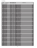
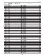
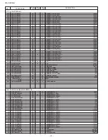
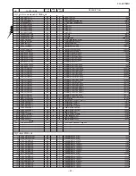
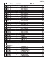
FO-2970MU

– 24 –

[13] Printer PWB unit

98

VRD-HT2EY103J

AA

C

Resistor(1/4W 10K


±

5%)

[R17]

99

VRD-HT2EY203J

AA

C

Resistor(1/4W 20K


±

5%)

[R18]

100

VRD-HT2EY203J

AA

C

Resistor(1/4W 20K


±

5%)

[R19]

101

VRD-HT2EY103J

AA

C

Resistor(1/4W 10K


±

5%)

[R20]

102

VRD-HT2EY122J

AA

C

Resistor(1/4W 1.2K


±

5%)

[R21]

103

VRD-HT2EY122J

AA

C

Resistor(1/4W 1.2K


±

5%)

[R22]

104

VRD-HT2EY122J

AA

C

Resistor(1/4W 1.2K


±

5%)

[R23]

105

VRD-HT2EY122J

AA

C

Resistor(1/4W 1.2K


±

5%)

[R24]

106

VRD-HT2EY122J

AA

C

Resistor(1/4W 1.2K


±

5%)

[R25]

107

VRD-HT2EY122J

AA

C

Resistor(1/4W 1.2K


±

5%)

[R26]

108

VRD-HT2EY221J

AA

C

Resistor(1/4W 220


±

5%)

[R27]

109

VRD-HT2EY103J

AA

C

Resistor(1/4W 10K


±

5%)

[R28]

110

VRD-HT2EY104J

AA

C

Resistor(1/4W 100K


±

5%)

[R29]

111

VRNHT2EK1102F

AA

C

Resistor(1/4W 11.0K


±

1%)

[R30]

112

VRD-HT2EY203J

AA

C

Resistor(1/4W 20K


±

5%)

[R31]

113

VRD-HT2HY3R0J

AB

C

Resistor(1/2W 3.0


±

5%)

[R32]

114

VRD-HT2EY620J

AA

C

Resistor(1/4W 62


±

5%)

[R33]

115

VRD-HT2EY681J

AA

C

Resistor(1/4W 680


±

5%)

[R34]

116

VRD-HT2EY103J

AA

C

Resistor(1/4W 10K


±

5%)

[R36]

117

VRD-HT2EY474J

AA

C

Resistor(1/4W 470K


±

5%)

[R37]

118

VRD-HT2EY105J

AA

C

Resistor(1/4W 1.0M


±

5%)

[R38]

119

VRD-HT2EY512J

AA

C

Resistor(1/4W 5.1K


±

5%)

[R39]

120

VRD-HT2EY561J

AA

C

Resistor(1/4W 560


±

5%)

[R40]

121

VRD-HT2EY334J

AA

C

Resistor(1/4W 330K


±

5%)

[R41]

122

VRD-HT2EY221J

AA

C

Resistor(1/4W 220


±

5%)

[R42]

123

VRS-HT3AAR56J

AB

C

Resistor(1W 0.56


±

5%)

[R43]

124

VRD-HT2EY102J

AA

C

Resistor(1/4W 1.0K


±

5%)

[R44]

125

VRD-HT2EY102J

AA

C

Resistor(1/4W 1.0K


±

5%)

[R45]

126

VRS-HT3AAR56J

AB

C

Resistor(1W 0.56


±

5%)

[R46]

127

VRD-HT2EY153J

AA

C

Resistor(1/4W 15K


±

5%)

[R47]

128

VRD-HT2EY472J

AA

C

Resistor(1/4W 4.7K


±

5%)

[R48]

129

VRD-HT2EY512J

AA

C

Resistor(1/4W 5.1K


±

5%)

[R49]

130

VRD-HT2EY561J

AA

C

Resistor(1/4W 560


±

5%)

[R50]

131

VRD-HT2EY105J

AA

C

Resistor(1/4W 1.0M


±

5%)

[R51]

132

VRHDPT3AF395J

AD

C

Resistor(1W 3.9M


±

5%)

[R52]

133

VRH-PT2HF395J

AC

C

Resistor(1/2W 3.9M


±

5%)

[R53]

134

VRD-HT2HY3R0J

AB

C

Resistor(1/2W 3.0


±

5%)

[R54]

135

VRD-HT2EY620J

AA

C

Resistor(1/4W 62


±

5%)

[R55]

136

VRHYKU3AD257K

AH

C

Resistor(1W 250M


±

10%)

[R56]

137

VRHAKU2HD107J

AF

C

Resistor(1/2W 100M


±

5%)

[R57]

138

VRHAKU2HD207J

AF

C

Resistor(1/2W 200M


±

5%)

[R58]

139

VRHAKU2HD825J

AF

C

Resistor(1/2W 8.2M


±

5%)

[R59]

140

VRD-HT2EY000J

AA

C

Resistor(1/4W 0


±

5%)

[R60]

141

RTRNZ0022GCZ1

AL

B

H/V transformer(Z0022)

[T1]

142

RTRNZ0021GCZZ

AL

B

H/V transformer(Z0021)

[T2]

143

QTANN2046SCZZ

AC

C

Terminal(N2046)

[TC]

144

RVR-M1615QCZZ

AC

C

Variable resistor

[VR1]

145

RVR-M251AQCZZ

AC

C

Variable resistor

[VR2]

146

VHED2.4ESAB11

AC

B

Zener diode(RD2.4ES)

[ZD1]

147

VHERD30JSAB21

AC

B

Zener diode(RD30JS)

[ZD2]

148

VHERD30JSAB21

AC

B

Zener diode(RD30JS)

[ZD3]

149

VHED2.4ESAB11

AC

B

Zener diode(RD2.4ES)

[ZD4]

150

VHE1ZB200Y/-1

AF

B

Zener diode(1ZB200Y)

[ZD5]

151

VHERD100E//-1

AC

B

Zener diode(RD100E)

[ZD6]

152

VHERD100E//-1

AC

B

Zener diode(RD100E)

[ZD7]

(Unit)

901

DCEK-224CSC01

BG

E

Printer PWB unit

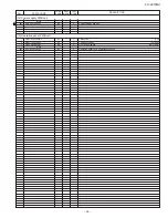
[14] Power supply PWB unit

1

0KY0L551A0010

AE

C

Ferrite beads(BL02RN1)

[BEA1]

2

0KY0C245Q1040

AM

C

Film capacitor(250WV 0.1

µ

F)

[C1]

3

0KY0C245Q1040

AM

C

Film capacitor(250WV 0.1

µ

F)

[C3]

4

0KY0C344K2210

AV

C

Electrolytic capacitor(220PF)

[C5]

5

0KY0C176Q1020

AF

C

Ceramic capacitor(1000PF)

[C6]

6

0KY0C176Q1030

AN

C

Ceramic capacitor(0.01

µ

F)

[C7]

7

0KY0C1A9R2210

AG

C

Ceramic capacitor(1KWV 220PF)

[C8]

8

0KY0C251E1030

AE

C

Film capacitor(50WV 0.01

µ

F)

[C9]

9

0KY0C251E4720

AE

C

Film capacitor(50WV 4700PF)

[C10]

10

0KY0C151E1010

AE

C

Ceramic capacitor(50WV 100PF)

[C11]

11

0KY0C176Q1020

AF

C

Ceramic capacitor(1000PF)

[C15]

12

0KY0C162E1040

AF

C

Ceramic capacitor(50WV 0.1

µ

F)

[C22]

13

0KY0C3A0D3310

AM

C

Electrolytic capacitor(330PF)

[C101]

14

0KY0C3A0D3310

AM

C

Electrolytic capacitor(330PF)

[C103]

15

0KY0C162E1040

AF

C

Ceramic capacitor(50WV 0.1

µ

F)

[C105]

16

0KY0C3A0B3310

AL

C

Electrolytic capacitor(330PF)

[C301]

17

0KY0C3A0D3300

AG

C

Electrolytic capacitor(33PF)

[C302]

Summary of Contents for FO-2970M

Page 1: ...s laser radiation is not a danger to the skin but when an exact focusing of the laser beam is achieved on the eyes retina there is danger of spot damage to the retina The following cautions must be observed to avoid exposure of the laser beam to your eyes at the time of servicing 1 When a problem in the laser optical unit has occurred the whole optical unit must be exchanged as a unit not an indiv...

Page 2: ...RAMS 1 Block diagram 4 1 2 Wiring diagram 4 2 3 Point to point diagram and connector signal name 4 3 CHAPTER 5 CIRCUIT DESCRIPTION 1 Circuit description 5 1 2 Circuit description of control PWB 5 2 3 Circuit description of TEL LIU and Hook SW PWB 5 21 4 Circuit description of power supply PWB 5 23 5 Circuit description of CIS UNIT 5 24 CHAPTER 6 CIRCUIT SCHEMATICS AND PARTS LAYOUT 1 Control PWB ci...

Page 3: ...406 lines inch 16 lines mm Vertical 391 lines inch 15 4 lines mm PC Printing 600 dpi enhanced 1 800 dpi Input document size Automatic feeding Width 5 8 to 8 5 148 to 216mm Length 5 5 to 11 140 to 279mm Manual feeding Width 5 8 to 8 5 148 to 216mm Length 5 5 to 39 4 mm 140 to 1 000mm Effective Scanning width 8 3 210 mm max Effective Printing width 8 0 208 mm max Reception modes Fax Tel A M Scanning...

Page 4: ... 0 PAPER CHECK TONER EMPTY PC IN USE LINE IN USE REDUCTION ENLARGEMENT COPY HELP START STOP TEL FAX A M FUNCTION VOLUME DOWN UP RECEPTION MODE RESOLUTION BROADCAST 01 02 03 04 08 07 06 05 12 11 10 09 16 POLL 15 14 13 20 G4 19 G3 18 G2 17 G1 1 2 3 4 7 8 9 13 14 15 16 20 19 21 17 18 22 10 11 12 5 6 13 14 15 16 17 18 19 20 21 22 BROADCAST key Press this key to send a document to a group of receiving ...

Page 5: ...PWB 2 High voltage power adjustments The high voltage power adjustments are composed of the MC output voltage adjustment and the DC bias output voltage adjustment Either adjustment is performed with the diag function MAIN CHG ADJUST MODE 1MC output voltage adjustment In the measurement circuit shown below adjust VR1 to be 1050V 1200V aim at 1100V MC Measure with the high voltage tester effective v...

Page 6: ...put voltage check DRUM DC Bias 3Transfer charger voltage check After MC output voltage adjustment and DC bias output voltage ad justment check transfer charger voltage Check that the output voltage is 3200V 3700V For measurement use a high voltage tester effective value meter Transfer charger Output voltage check DRUM D7 D8 Note For measurement do not remove Printer PWB from the bottom plate VR1 M...

Page 7: ...TTING PRESS or KEY DIAL MODE 1 TONE 2 PULSE KEY KEY DISPLAY step 4 End using the STOP key step 3 Select using 1 or 2 step 2 Select DIAL MODE Push until DIAL MODE is indicated because the number of s changes by the models 1 2 PULSE SELECTED STOP 1 F100 ICPS10 is installed in order to protect IC s from and overcurrent generated in the verification stamp drive circuit If F100 is open replace it with ...

Page 8: ...pecifications FUNC 9 8 6 START 01 AREA PRINT MODE START 02 CHECK PATTERN 1 START 03 CHECK PATTERN 2 START 04 CHECK PATTERN 3 START 05 PAPER FEED AGING START 06 LIFE SET MODE START 07 LIFE ALL CLEAR START START 08 LIFE ENTRY MODE START 09 TOP ADJUST MODE START START Then press the key Select the desired item with the key and the key or select with the rapid key Enter the mode with the key START 10 ...

Page 9: ...switch mode screen Switch No 1 2 3 4 5 6 7 DATA No 8 Data S O F T S W I T C H M O D E S W 0 1 0 0 1 0 0 0 0 0 S O F T S W I T C H M O D E S W 1 S O F T S W I T C H M O D E S W 1 6 0 0 0 1 0 1 1 0 1 6 The buzzer beep pattern is on for 0 25 seconds and then off for 0 25 seconds 3 Aging mode If any document is set up in the first state when started copying will be executed If it is not set up check p...

Page 10: ...10 14400bps V 34 2 33600bps V 34 11 12000bps V 34 3 31200bps V 34 12 9600bps V 34 4 28800bps V 34 13 7200bps V 34 5 26400bps V 34 14 4800bps V 34 6 24000bps V 34 15 2400bps V 34 7 21600bps V 34 16 0 300bps V 21 8 19200bps V 34 17 ANsam V 8 9 16800bps V 34 18 END AUTO FEEDER MODE AUTO FEEDER MODE A4 A4 ORG After setup of the document Only the sensor which is activated fallen down is displayed The p...

Page 11: ...R 0 0 1 2 3 0 L F Rapid key 07 Life all clear The mode is used to clear the life counter of the printer of the counter of the auto feeder Note The counter shows the operational state of the printer e g how many sheets have been printed since start of use The ordi nary memory does not reset the counter Accordingly it is nec essary to reset this counter in addition to the ordinary memory clear if th...

Page 12: ...red using the or key if desired Press the STOP key to exit from the mode Note The counter shows the operational state of the printer how many sheets have been printed since start of use and others The ordinary memory does not reset the counter Accordingly it is necessary to reset the counter or do the clear process in addi tion to the ordinary memory clear if the content in the memory on the contr...

Page 13: ...0 0 0 0 S F T S W 1 1 0 0 0 0 0 0 0 S F T S W 1 1 0 0 0 0 0 0 0 S F T S W 1 1 0 0 0 0 0 0 0 S F T S W 2 0 0 0 0 0 0 0 0 S F T S W 65 0 0 0 0 0 0 0 0 Press key during setting To finish the settings halfway between SW 1 and SW65 press the STOP key In this case the setting being done to the SW No on display will be nullified while settings done to the preceding SW Nos remain in effect The soft switch...

Page 14: ... 6 mode No 5 6 7 8 0 7 0 OFF 0 0 0 0 off 0 8 0 Communication results printout Error Err Tmr Mem Send only No print Always OPTION 1 transaction report No 1 0 0 0 1 1 0 2 No 2 0 0 1 0 1 0 3 No 3 1 0 0 0 0 1 4 Delay timer before line connect in auto dial 3 sec 0 sec 0 SW4 Delay timer of after line connect in auto dial 3 6 sec 3 0 sec 1 7 sec 3 0 sec 5 No 5 1 1 0 0 0 6 No 6 1 0 1 0 1 Number of CNG det...

Page 15: ... 1 Reception No 1 0 0 1 1 0 2 No 2 0 1 0 1 0 3 Dial pausing sec pause 2sec 4sec 1 SW8 4 Signal transmission level Binary input 16 8 4 2 1 0 5 No 4 5 6 7 8 1 6 0 1 0 0 1 9 dBm 0 7 0 8 1 CED tone signal interval 75 ms 500 ms 750 ms 1000 ms 1 No 1 0 0 1 1 0 2 No 2 0 1 0 1 0 3 Equalizer freeze control MODEM On Off 0 SW9 4 Equalizer freeze conditions All 7200 bps 0 5 CED detection time 500 ms 1000 ms 0...

Page 16: ...MF signal transmission level Low Binary input 16 8 4 2 1 0 2 No 1 2 3 4 5 1 3 0 1 1 0 0 6 dBm 1 4 0 SW12 5 0 6 Reserved 0 7 Reserved 0 8 Reserved 0 1 DTMF signal transmission level High Binary input 16 8 4 2 1 0 2 No 1 2 3 4 5 1 3 0 1 0 0 0 4 dBm 0 4 0 SW13 5 0 6 Reserved 0 7 Reserved 0 8 Reserved 0 1 Reserved 0 2 Reserved 0 3 Reserved 0 SW14 4 Reserved 1 5 Reserved 1 6 Reserved 0 7 Reserved 0 8 R...

Page 17: ...NC 3 SW18 4 Sender s phone number setting Cannot change Change allowed 0 5 Polling key Yes No 0 OPTION 6 Activity report print Automatic printout No printout when memory full 0 OPTION 7 Total communication hours and pages print Off On 0 8 Line density selection Fine Standard 0 OPTION Density adjustment when Fine STD mode Normal Faint Deep Deep when Dark mode 1 No 1 0 0 1 1 0 2 No 2 0 1 0 1 0 Densi...

Page 18: ...OPTION 6 tel 0 9 No 5 6 7 8 Data No 1 7 EX 0 1 0 1 0 8 eg 5 1 1 Busy tone detection ON OFF time Shorter duration 350ms 150 ms 0 Busy tone detection ON OFF time 650 ms 900 ms 2700 ms 900 ms 2 Longer duration No 2 0 0 1 1 0 3 No 3 0 1 0 1 1 SW25 4 Busy tone continuous sound detect time 10 sec 5 sec 1 5 Busy tone detect continuation sound detect No Yes 0 6 Busy tone detect intermittent sound detect N...

Page 19: ...5 Reserved 0 6 Reserved 0 7 Reserved 0 8 Reserved 0 1 Reserved 0 2 Reserved 0 3 Reserved 0 SW29 4 Reserved 0 5 Reserved 0 6 Reserved 0 7 Reserved 0 8 Reserved 0 1 Reserved 0 2 Reserved 0 3 Reserved 0 SW30 4 Reserved 0 5 Reserved 0 6 Reserved 0 7 Reserved 0 8 Reserved 0 1 Reserved 0 2 Reserved 0 3 Reserved 0 SW31 4 Reserved 0 5 Reserved 0 6 Reserved 0 7 Reserved 0 8 Reserved 0 SW NO DATA NO ITEM Sw...

Page 20: ...d 0 8 Reserved 1 1 Reserved 1 2 Reserved 1 3 Reserved 0 SW35 4 Reserved 1 5 Reserved 1 6 Reserved 1 7 Reserved 0 8 Reserved 1 1 Reserved 1 2 Reserved 1 3 Reserved 1 SW36 4 Reserved 1 5 Reserved 1 6 Reserved 1 7 Reserved 0 8 Reserved 0 1 Reserved 0 2 Reserved 0 3 Reserved 0 SW37 4 Reserved 0 5 Reserved 0 6 Reserved 0 7 Reserved 0 8 Reserved 0 1 Reserved 0 2 Reserved 0 3 Reserved 0 SW38 4 Reserved 0...

Page 21: ...d 0 8 Reserved 0 1 Reserved 0 2 Reserved 0 3 Reserved 0 SW42 4 Reserved 0 5 Reserved 0 6 Reserved 0 7 Reserved 0 8 Reserved 0 1 Reserved 0 2 Reserved 0 3 Reserved 0 SW43 4 Reserved 0 5 Reserved 0 6 Reserved 0 7 Reserved 0 8 Reserved 0 1 Reserved 0 2 Reserved 0 3 Reserved 0 SW44 4 Reserved 0 5 Reserved 0 6 Reserved 0 7 Reserved 0 8 Reserved 0 1 Reserved 0 2 Reserved 0 3 Reserved 0 SW45 4 Reserved 0...

Page 22: ...d 0 8 Reserved 0 1 Reserved 1 2 Reserved 0 3 Reserved 0 SW49 4 Reserved 0 5 Reserved 0 6 Reserved 0 7 Reserved 0 8 Reserved 0 1 Reserved 0 2 Reserved 0 3 Reserved 0 SW50 4 Reserved 0 5 Reserved 0 6 Reserved 0 7 Reserved 0 8 Reserved 0 1 Reserved 0 2 Reserved 0 3 Reserved 0 SW51 4 Reserved 0 5 Reserved 0 6 Reserved 0 7 Reserved 0 8 Reserved 0 1 Reserved 0 2 Reserved 0 3 Reserved 0 SW52 4 Reserved 1...

Page 23: ...n On Off 1 2 V 34 mode function On Off 1 3 V 34 control channel communication speed 2400 bps 1200 bps 0 SW55 4 Reserved 0 5 Reserved 0 6 Reserved 0 7 Reserved 0 8 Reserved 0 1 Reserved 0 2 Reserved 1 3 Reserved 1 SW56 4 Reserved 0 5 Reserved 0 6 Reserved 0 7 Reserved 0 8 Reserved 0 1 Reserved 1 2 Reserved 1 3 Reserved 1 SW57 4 Reserved 1 5 Reserved 1 6 Reserved 1 7 Reserved 0 8 Reserved 0 1 Reserv...

Page 24: ... SW62 4 Reserved 1 5 Reserved 0 6 Reserved 0 7 Reserved 1 8 Reserved 1 1 Reserved 0 2 Reserved 1 3 Reserved 0 SW63 4 Reserved 0 5 Reserved 0 6 Reserved 1 7 Reserved 1 8 Reserved 0 1 Reserved 0 2 Reserved 0 3 Reserved 1 SW64 4 Reserved 0 5 Reserved 0 6 Reserved 0 7 Reserved 0 8 Reserved 1 1 Reserved 0 2 Reserved 0 3 Reserved 1 SW65 4 Reserved 0 5 Reserved 0 6 Reserved 0 7 Reserved 0 8 Reserved 1 SW...

Page 25: ...n the line connection and dial data output under the auto dial mode SW4 No 7 No 8 Number of CNG detect STAND BY mode Used for detection of CNG in 1 to 4 pulses SW5 No 1 Time format When this switch is set to 0 time is displayed in 12 hour system When set to 1 24 hour system SW2 No 4 CNG detection in stand by mode The CNG signal detection function during stand by stops 0 Yes 1 No SW2 No 5 Polling s...

Page 26: ...ssion problem It may be useful for overseas communication to avoid an echo sup pression problem if set to 1 SW7 No 5 EOL detect timer 25 seconds or 13 seconds are selected for the detection timer of EOL end of line This is effective against communication trouble on a spe cific type of long EOL 0 13 seconds 1 25 seconds SW7 No 6 Protocol monitor Normally set to 0 If set to 1 communication can be ch...

Page 27: ...NG transmission by pressing the Start key in the key pad dialing mode When set to 1 CNG transmis sion in the key pad dialing mode cannot be performed In either case CNG transmission can be performed in the auto dial mode SW11 No 5 Error criterion Used to select error criterion for sending back RTN when receiving im age data SW11 No 6 Pulse to tone change by When setting to 1 the mode is changed by...

Page 28: ...esolution key is manually set to another mode SW19 No 1 No 2 Density adjustment when Fine STD mode This is used for density adjustment in fine standard mode Adjust the density according to that of frequently used original Set to Dark for darker reading either in the auto or the dark mode of light original Set to Light for lighter reading either in the auto or the dark mode of dark original Set to ...

Page 29: ...mit can be set in the range of 650msec to 2700msec SW25 No 4 Busy tone continuous sound detect time Set detecting time busy tone for 5 seconds or as is PTT SW25 No 5 Busy tone detect continuation sound detect Used to select detection of the continuous sound of certain frequency SW25 No 6 Busy tone detect intermittent sound detect Used to select detection of the intermittent sound of certain freque...

Page 30: ... channel communication speed Used to select the control channel communication speed for V 34 mode SW55 No 4 No 8 Reserved Set to 0 SW56 No 1 Reserved Set to 0 SW56 No 2 No 3 Reserved Set to 1 SW56 No 4 No 8 Reserved Set to 0 SW57 No 1 No 6 Reserved Set to 1 SW57 No 7 No 8 Reserved Set to 0 SW58 No 1 No 8 Reserved Set to 0 SW59 No 1 No 4 Reserved Set to 1 SW59 No 5 No 8 Reserved Set to 0 SW60 No 1 ...

Page 31: ...on problems still exist on the machine use the following format and check the related matters TO ATT Ref No CC ATT Date FM Dept Sign Facsimile communication problem Ref No Date From Mr Fax Tel No Our customer Name Tel No Address Fax No Contact person Model name Other party Name Tel No Address Fax No Contact person Model name Problem mode Line Domestic international Mode G3 Phase A B C D Reception ...

Page 32: ...rror occurred after a response to retransmission end command was received G3 Reception Code Final received signal Error Condition Receiver side 0 Incomplete signal frame Cannot recognize bit stream after flag 1 NSS DCS Cannot recognize CFR or FTT signal Disconnects line during transmission line error 2 NSC DTC Cannot recognize NSS signal FIF code etc 3 EOP Cannot recognize MCF PIP PIN RTN RTP sign...

Page 33: ...han 97 C even while printing E 29 Handshaking error in V 8 negotiation procedure E 30 Handshaking error in V 34 line probing procedure E 31 Handshaking error in V 34 HDX training procedure Error Code Transmission Errors Reception Errors E 16 Same as E 0 Same as E 0 E 17 Same as E 1 Same as E 1 E 18 Same as E 2 Same as E 2 E 19 Same as E 8 E 20 Same as E 4 Same as E 9 E 21 Same as E 10 E 22 E 23 Sa...

Page 34: ...4M bit DRAM ONLY PC PRINT THERMISTER TEL LIU PWB CIS SCANNER MOTOR CNRTH CNLIU CNCIS OPERATION PANEL PWB LCD CNMT CNPN SPEAKER CNSP ASIC LR38784 TONER SENSOR PICK UP SOLENOID LASER UNIT PAPER FEED MOTOR FAN MOTOR PRINTER PWB PERSONAL COMPUTER CNPL CNTNR CNLSU CNMMT POWER PWB HEATER LAMP CNFM CNHT CNPW CONTROL PWB CNPRT SENTRONICS CABLE BAT ...

Page 35: ... CNHS1 CNLIUA CNHS2 TONER SENSOR CNSP CNCIS CIS TX MOTOR 7 2 22 OPERATION PANEL PWB LCD 14 6 CONTROL PWB 50 PRINTER PWB PRINTER MOTOR 4 AUTO POWER CONTROL PWB 9 5 3 LASER SCANING MOTOR BEAM DETECTOR PWB LSU UNIT PICKUP SOLENOID 5 2 36 FAN MOTOR 3 PC 12 2 HEATER LAMP 2 POWER SUPPLY UNIT CNFUSE THERMAL FUSE UNIT 3 CNRTH THERMISTOR 2 HOOK SWITCH PWB 2 TEL LINE TEL LIU PWB 12 SPEAKER CNLCD ...

Page 36: ... 1 2 3 4 5 6 7 8 9 24V DG VIDEO SAMP SYNC APCSTT PMCLK PMD PE CNPC 1 2 3 4 5 6 7 8 9 10 11 12 13 14 15 16 17 18 19 20 21 22 23 24 25 26 27 28 29 30 31 32 33 34 35 36 NSTOROBE DATA1 DATA2 DATA3 DATA4 DATA5 DATA6 DATA7 DATA8 NACK BUSY PERROR SELECT NAUTOFD N C DG DG PLH DG DG DG DG DG DG DG DG DG DG DG DG NINIT NFAULT N C N C N C NSELECTON CNTNR 1 2 3 4 5 5V TSEN DG N C FG POUT PWMSIN PIN DOP TSEN 2...

Page 37: ...fer within the RAM and encoded and stored in the transmit buffer of the RAM The data is then converted from parallel to serial form by the modem where the serial data is modulated and sent onto the line Receive operation There are two ways of starting reception manual and automatic Depression of the START key in the off hook mode in the case of manual receive mode or CI signal detection by the LIU...

Page 38: ... POE2 CASH PB5 IRQ3 POE3 RDWR PB6 IRQ4 A18 BACK PB7 IRQ5 A19 BREQ PB8 IRQ6 A20 WAIT PB9 IRQ7 A21 ADTRG PA2 SCK0 DREQ0 IRQ0 PA6 TCLKA CS2 PA7 TCLKB CS3 PA8 TCLKC IRQ2 PA9 TCLKD IRQ3 PA10 CS0 PA11 CS1 PA14 RD PA13 WRH P L L PF0 AN0 PF1 AN1 PF2 AN2 PF3 AN3 PF4 AN4 PF5 AN5 PF6 AN6 PF AN7 PE5 TIOC1B PE6 TIOC2A PE7 TIOC2B PE8 TIOC3A PE9 TIOC3B PE10 TIOC3C PE11 TIOC3D PE12 TIOC4A PE13 TIOC4B MRES PE14 TI...

Page 39: ...el onto this terminal power on reset condition is attained MRES 144 I Manual reset When applying low level to this terminal manual reset condition is obtained WDTOVF 44 O Watch dog timer Overflow output signal from WDT overflow BREQ 33 38 I Bus right demand Low level obtained when external device demands to release the bus right BACK 30 37 O Bus right demand Shows that the bus right has been relea...

Page 40: ...f data CASHL 29 O HL column address Timing signal for column address strobe of DRAM QFP 144 strobe It is output when accessing bits 23 to 16 of data Multi function TCLKA 51 54 I MTU timer clock input External clock input terminal for MTU counter timer pulse unit TCLKB TCLKC TCLKD TIOC0A 109 111 I O MTU input capture Channel 0 terminal for inputting Input Capture outputting Output TIOC0B 113 output...

Page 41: ...ger input to start A D conversion trigger input I O port POE0 31 32 34 36 I Port output enable Input terminal to enable general port to control driving of port POE3 terminal in case of setting output PA0 PA15 1 3 4 33 43 I O General port General input output port terminal to specify input output by every bit QFP 112 47 54 100 PA0 PA23 101 107 QFP 144 130 134 136 PB0 PB9 25 27 31 32 I O General por...

Page 42: ...g motor control This function outputs the sending motor control signals of 2 or 1 2 phase excitation to the motor driver 7 Buzzer and Ringer control This function outputs a buzzer 1042Hz or a ringer controlled sig nal signal 8 Laser signal control This function controls to output laser beam 9 Protection circuits LR38784Ahas protection circuits for a pick up solenoid and a heater Pin No I O Signal ...

Page 43: ... TC_BIASON 130 O PUS 131 O MCON 132 I PE 133 O PMDZ 134 O APCSTT 135 ICS SYNCZ 136 O SMAP 137 GND Pin No I O Signal name 46 I DRAK1 47 O DREQ0Z 48 O DREQ1Z 49 GND 50 IS SHCK 51 GND 52 GND 53 VDD 54 VDD 55 O RESET2Z 56 O USOUT 57 O2M INT1Z 58 O INT2Z 59 O2M INT3Z 60 O2M INT4Z 61 O INT5Z 62 I RDZ 63 I WRHZ 64 I WRLZ 65 I CS2Z 66 I CSIZ 67 IS WDTOVFZ 68 O RTCIO 69 O RTCCE 70 GND 71 O RTCCK 72 IOR RTC...

Page 44: ...XBPINI 164 GND 165 O12M BPOPE 166 O12M BPOSE 167 O12M XBPOFT 168 I XBPSEI 169 GND 170 VDD 171 IS PRTCLK 172 IOR D0 173 IOR D1 174 IOR D2 175 IOR D3 176 IOR D4 177 IOR D5 178 IOR D6 179 IOR D7 180 GND 181 IOR D8 182 IOR D9 183 IOR D10 Pin No I O Signal name 184 IOR D11 185 IOR D12 186 IOR D13 187 IOR D14 188 IOR D15 189 GND 190 I A21 191 I A20 192 I A13 193 I A12 194 I A11 195 IOR A10 196 IOR A9 19...

Page 45: ...e Scanning motor IEEE1284 I F Connector Reset circuit PIN sensor POUT sensor PE sensor Door switch CPU SH7041 and ASIC LR38784A Host computer Thermistor The PCU controls the following functions and items 1 Rotation of the main motor pulse motor 2 High voltage output 3 Fusing temperature 4 Optical system polygon motor laser APC circuit start 5 400 600DPI resolution automatic selection 6 Temperature...

Page 46: ...detection The diagram below shows timings of clutch operation 0 5 1 25 1 534 2 334 3 366 0 991 PUS PIN 0 1 0 8 0 45 0 5 1 534 0 8 c Electrical connection In the paper feed and transportation system drive parts and sensors are connected as shown in the figure below 137 MB 60 MEN CPU SH7041 CONTROL PWB PRINTER PWB 116 MA 24V MA 1 CNMMT 5V 5V MA 2 MB 3 MB 4 8 7 14 13 4 17 1 2 24V 1 PUS 2 IC1 CNPL 130...

Page 47: ...ns former PWMSIN This signal is to control the main charger voltage and the transfer charger voltage The PWM pulse of 295 28Hz is outputted This pulse waveform adds the AC component to the main charger volt age and the transfer charger voltage By changing the pulse duty of this signal the main charger voltage and the transfer charger voltage are controlled during temperature correction operation W...

Page 48: ...tor ON OFF signal APCSTT Used to start the laser beam generation circuit SYNC This signal is outputted when the laser beam scanned by the laser beam sensor signal is sensed by sensor Photo diode D601 Used for the left margin control VIDEO This signal is used to control the laser diode emitting Not only when the laser beam is emitted to perform the LEND proc ess but also when the laser beam is emit...

Page 49: ...e CPU detects the scanning position with the SYNC signal the dummy laser beam becomes unnecessary 3 The draw signal Video_ is made from the DDATA_ signal of one line outputted from theASIC When it is outputted the laser beam is turned on off accordingly This corresponds to the making of latent electro static images on the photoconductor drum 4 When making of latent electrostatic images for one lin...

Page 50: ...ven in synchronization with the VIDEO signal sent from the CPU board By the operation of the laser diode control board infrared laser beams of 780nm are outputted from the laser diode and made in parallel by the collimator lens and focused onto the scanning motor by the first cylin der lens The scanning mirror rotation is controlled by the scanning motor to be constant at 11811rpm 600dpi and 8000r...

Page 51: ...ting CDPAGE Printing started Base machine Printing started Printing started HLON FAN OFF 120s 155 C Temperature control started Printing finished In case of PC printing Single sheet continuous CDPAGE PC printing started The Heater ON timing is set during Zero Cross interrupt 2 Protect against overheat Though the heater lamp ON signal HLON is normal if triac PD101 and T2 are kept ON overheat may re...

Page 52: ...ture rises abnormally high 187 C 131 CNPRT PRINTER PWB POWER PWB CONTROL PWB 2 15 HLON 127 1 16 RTH CNLN HLL 1 CNHT 5V IC1 PWRLY ASIC LR38784A CPU SH7041 118 HLN 3 CNHT ACL 1 2 ACN 5V 1 CNRTH 2 RTH 24V 24VS 24V 1 CNFUSE 3 24VS Driver Temperature fuse 132 C Temperature fuse 187 C Heater lamp Thermistor CNPW HLON PWRLY The heat roller surface temperature is maintained to the optimum level by control...

Page 53: ...MD APCSTT LEND HSYNC LDATAEN LD_ MCON ACSIN PUS PIN POUT Tc BiasON MM ON ON 3 5 1 0 68 DC ON LEND_ Hard control start LEND_ Hard control end 5 6 Generation 3 0 PMD APCSTT LEND_ HSYNC_ LDATAEN LD_ MC ON 5 0 OFF OFF Cleaning OFF ACSIN TC Bias TC Bias HLON DREADY_ DPAGE_ output voltage Printing process Pre revolution processing Timing from DPAGE internal signal of ASIC to BIAS ON pre revolu tion proc...

Page 54: ...o ITU T V 17 V 21 V 23 V 27ter V 29 and V 34 specifications It also complies with V 8 and T 30 binary signaling conditions This mo dem supports HDLC internally Therefore products using built in error correction and the T 30 protocol do not need an external serial input output SIO line on DTE This modem can execute HDLC framing as specified in T 30 at all data rates Since it can perform zero insert...

Page 55: ...S GND 100 PLL GND GND PIN Signal Name I O Type Interface 3 1 RESERVED 2 RS2 IA Host interface 3 RS3 IA Host interface 4 RS4 IA Host interface 5 CS IA Host interface 6 WR IA Host interface 7 RD IA Host interface 8 RDCLK OA DTE Serial interface 9 RLSD OA DTE Serial interface 10 TDCLK OA DTE Serial interface 11 TXD IA DTE Serial interface 12 CTS OA DTE Serial interface 13 VDD1 PWR 14 RESERVED 15 RESE...

Page 56: ...fier monitors the line under the on hook mode out puts the buzzer sound generated from the SH7041 ringer sound DTMF generated from the modem and line sound o Adjustment of voice ringer volume The voice ringer volume can be adjusted by using the panel buttons UP and DOWN The ringer volume can be adjusted in the Stand by mode by pressing the UP DOWN button The reception level can be adjusted by pres...

Page 57: ...tch RHS is determined from the logical level of RHS signal RHS is in the hook SW PWB RHS LOW ON HOOK RHS HIGH OFF HOOK External telephone hook status detection circuit HS This circuit comprises the photo coupler PC1 resistors R1 and R2 Zener diodes ZD1 and ZD2 When an external telephone is connected and enters the on hook mode the LED of photo coupler PC1 emits light and the light receiv ing eleme...

Page 58: ...e control PWB Set the line driver of MODEM FM336 to 6 dBm Speaker volume control signal VOL A VRSEL1 VRSEL2 matrix VOL B VOL C The circuit is located in the control PWB GAIN C Reception gain switching signal The circuit is located L When connected to line 1 1 gain in the control PWB H When not connected to line HIGH gain BZCONT Speaker output signal switching The circuit is located H Buzzer signal...

Page 59: ...g to output load As load increases ON period becomes longer Constant voltage is controlled by applying feedback to the control circuit via photo coupler from 24 V output The overcurrent protective circuit detects prolonged ON period caused by excessive output load lengthens Q1 OFF period by using the control circuit and restricts energy stored in the primary winding of transformer T1 Increase of t...

Page 60: ...signal SI CLK from the control PWB the trans ferred photoelectric analog signal SIG is impedance converted and the signal AIN is supplied to the control PWB 2 Waveforms 1 CLK SI SIG signals within the control PWB CLK SI 5 msec line SIG 1 2 3 1720 1721 1722 5V GND AiN CIS OUTPUT CIRCUIT emitter follower SIG SH CISCLK VLED GLED Fig 26 Fig 27 5 24 AC IN F1 RECTIFIED SMOOTHING CIRCUIT T1 TRANSFORMER 5...

Page 61: ... R204 68 RESET C222 1000P DG C220 C219 DG N M DG R236 10K R235 10K DG DG 8 7 6 5 1 2 3 4 BR19 10K x 4 5V SHCK R2 33 R3 33 C63 C62 N M DG R240 3K C226 470P C224 0 1 PLLVCC PLLVSS DG C162 27P C163 22P X1 6 912MHz DG C217 0 1 5V CHK24V PIN DG N M CI RHS HS RTH R201 470 R168 270 R200 470 BR11 B 10K x 4 5V D107 DA204K 5V R333 2K DG 5V DG C27 1000P C26 1000P C182 1000P MRES R172 4 7K DG BREQ BACK DG 5V ...

Page 62: ...70 R254 470 R271 47 R275 47 R278 47 R272 47 R273 47 R274 47 R276 47 R277 47 R279 47 R315 47 R301 47 R316 47 R302 47 R317 47 R304 47 R318 47 R305 47 PD7 PD6 PD5 PD4 PD3 PD2 PD1 PD0 PA9 PA8 PA7 PA6 PA5 PA4 PA3 PA2 PA1 PA0 PRAS PCAS PWR VIDEO SAMP APCSTT PMD MB MA LCDREQ HSYNC SYNC DG C286 470P 5V R280 1K R281 680 R256 68 12 13 14 7 DG 5V 10 11 14 7 DG 5V R257 0 DG R259 1M X4 20 95261MHz C260 10P C26...

Page 63: ...6 D5 D4 D3 D2 D1 D0 5V D 15 0 8 9 CS0 RD A20 R269 N M 12 VSS A2 A1 41 A8 A11 A12 A13 A14 A15 A16 A17 A18 A19 C43 0 1 DG IC21 BS62LV1024 2 31 3 28 4 25 23 26 27 5 7 8 9 10 11 24 29 22 30 21 20 19 18 17 15 14 13 32 A16 A15 A14 A13 A12 A11 A10 A9 A7 A6 A5 A4 A3 A0 OE W S1 S2 DQ8 DQ7 DQ6 DQ5 DQ4 DQ3 DQ2 DQ1 VCC A10 A9 A8 A7 A6 A5 A4 A3 A2 A1 A 16 1 D7 D6 D5 D4 D3 D2 D1 D0 VBAT D 7 0 12 RD WRL TCS1 R33...

Page 64: ... D0 R122 100 R121 68 R117 68 R227 68 R346 68 R347 68 R348 68 R349 68 R350 68 R345 100 MTP LCPD7 LCPD6 LCPD5 LCPD4 LCPD3 LCPD2 LCPD1 LCPD0 LCDREQ LCDACK0 C177 N M DG CISSI CISCLK 5V R119 10K R124 10K R123 33 R120 0 TP411 TP412 63 62 61 60 41 31 30 DALRH 38 42 44 34 5VR C108 0 01 C107 0 01 DG 10 24 56 DG 5V C64 0 1 C143 0 1 C22 0 1 C9 47 16 9 17 49 64 C142 0 1 C10 47 16 43 36 46 R191 100 R190 100 5V...

Page 65: ...P205 5V R382 10K R383 10K TP209 9 TP210 TP207 70 TP211 24 29 28 TXA2 TXA1 6 5B 6 5B C60 10 50 C386 0 1 15 58 59 66 82 51 33 25 98 100 3 3V DG R381 0 L102 0 1 2 C59 10 50 C53 0 1 MAG DG MAG R384 0 79 41 55 44 43 22 85 86 52 16 53 65 80 99 5V C45 0 1 C46 0 1 C47 0 1 C48 0 1 C371 0 1 C49 0 1 DG C50 0 1 C51 0 1 C52 0 1 DG D3 D2 D1 D0 D 7 0 A4 A3 A2 A1 A0 A 4 0 MDMCS 2 1D MDMWR 2 1D MDMRD 2 1D R374 100...

Page 66: ...24VA C1 4 7 50 DG 6 5 4 7 11 24VA DG C130 470P R137 62K C133 0 1 5VA D101 1SS355 K A SIGRX 5VA R328 10K R329 10K DG VREF 2 5V RCVOL DG 13 12 4 14 11 24VA DG C100 1000P R101 47K R327 3 3K R100 1 5K TELIN C131 1 R138 1 5K IC1B NJM2902M IC1D NJM2902M 0 1 16 10 15 8 2 1 5V DG IC7B HCF4053 0 1 16 11 14 8 12 13 5V DG IC7C HCF4053 R183 27K R218 11K C197 0 1 K SPKRP C165 0 1 K 5V 14 13 1 2 7 R212 390K 5V ...

Page 67: ... R323 10K R324 10K D103 HRW0502A R322 5 6K D102 1SS355 BAT CR2032 1 2 DG DG TPA TPB TPA TPB LAMPON 1 2 3 G COM 4 5 6 7 8 R133 10K DG MG 16 15 14 13 12 11 10 9 IC6 ULN2003A DG C189 1000P N M 24V ZD2 RD22FB3 F100 KAB2404 801 1 2 TX24V TXPA TXPB TXPA TXPB GLED 5VPN B E C Q102 2SA1036 R353 10K Q103 DTC114 B E C PNLON DG R209 R210 R211 R296 0 MG FG1 DG 5V 5V R355 N M R354 4 7K 1 2 3 D1 DAP202U FG3 R369...

Page 68: ...6 7 8 4 3 2 1 5 6 7 8 4 3 2 1 1 5I 1 6I R343 10K A0 A1 A2 A3 A4 A5 A6 A7 A8 A9 A10 A11 A12 A13 A14 A15 A16 A17 A18 A19 A20 A21 A 21 0 BR1 10K x 4 5V BR27 10K x 4 BR21 10K x 4 R270 10K BR14 10K x 4 BR28 10K x 4 D0 D1 D2 D3 D4 D5 D6 D7 D8 D9 D10 D11 D12 D13 D14 D15 D 15 0 BR12 10K x 4 5V BR29 10K x 4 BR13 10K x 4 BR30 10K x 4 C119 C252 C251 N M DG WRH WRL RD 1 4B 1 4B 1 4B Other block 8 9 ...

Page 69: ...LT NINIT VFM POUT C315 DG MG DG MG C313 C312 C309 C17 N M C308 0 1 PIN TSEN MEN MB SAMP APCSTT PMD MCON TC BIASON PWRLY R314 100 R313 100 R312 0 R311 200 R310 0 R309 0 R308 0 R307 0 CNPRT C343 C344 C330 24VS NSTROBE DATA2 DATA4 DATA6 DATA8 ZC BUSY SELECT NAUTOFD NSELECTIN C321 C297 C314 C311 C296 C295 C294 DG C293 0 1 DG 5V MG DG 24V C42 0 1 C19 N M C18 47 16 PLLVCC PLLVSS HLON PUS PE PMCLK SYNC V...

Page 70: ...FO 2970MU 6 10 Control PWB parts layout Top side ...

Page 71: ...FO 2970MU Control PWB parts layout Bottom side 6 11 ...

Page 72: ... 3 2 1 C106 560P R112 36K IC1 NJM2904D 5VA C111 1 R113 3 3K CNLIUA 8 CNLIUA 9 TXOUT RXIN DG R109 16K VREF MJ2 3 MJ2 4 EX TIP EX RING JP2 N M L4 R 5C JP3 N M L5 R 5C 1 2 3 C100 0 1 CNHS2 1 CNHS2 2 SW1 HOOK SW B M C RHS DG CNLIUA 7 1 3G RHS CNHS1 1 CNHS1 2 DG 24VA A K D2 1SS133 CNLIUA 4 CML Q102 DTC114EK DG CML 24VA CNLIUA 1 24VA CNLIUA 3 5VA 5VA VREF CNLIUA 2 DG C6 22 50 R106 1K R105 1K C4 47 50 DG...

Page 73: ...FO 2970MU 6 13 TEL LIU and Hook SW PWB parts layout Top side ...

Page 74: ...FO 2970MU 6 14 TEL LIU and Hook SW PWB parts layout Bottom side ...

Page 75: ...18SWH 3 6 18 16 2 4 17 1 R44 1K R45 1K CNMMT MA 1 2 3 4 MA MB MB DG C7 1000P C6 1000P C12 1000P C8 1000P 1 2 3 4 S4B PH KS MG MG MG MG R43 0 56 1W R46 0 56 1W C24 0 1 C23 0 1 9 8 7 6 5 4 3 2 1 G COM 10 11 12 13 14 15 16 IC1 ULN2003 24VH MG 2 4C MCON 2 3C PUS 2 3C TC BIASON 2 3C HLON 2 3C PWRLY 2 5C PWMSIN CNPL 24V 1 2 PUS 1 2 S2B PH K E 24V C44 1000P C45 1000P DG DG CNPW 5V 1 2 3 4 5 6 7 8 9 10 11...

Page 76: ... 3I 1 1F 1 6I 1 5I 1 5I 1 3I 1 3I 1 3I 1 3I 1 3I ZC 1 1F 5V 24VH 24V 5V R27 220 R42 220 1 3 2 4 DG 1 3 2 4 DG POUT PIN 24VP R14 20K R13 3 9K C4 0 1 DG DG 1 2 3 4 5 C43 100P A K D10 1SS133 5V DG FG R60 0 C42 0 1 5V TSEN DG N C FG CNTNR S5B PH KS 1 2 3 4 5 6 7 8 9 10 11 12 13 32 18 35 14 31 36 C28 100P C17 100P C16 100P C15 100P C13 100P DG 5V R7 1 2K R5 R8 1 2K R6 1 2K R4 1 2K C30 0 1 C27 C18 390P ...

Page 77: ...FO 2970MU 6 17 Printer PWB parts layout ...

Page 78: ...ON 10 4 SW101 R132 OPTION R131 OPTION R130 OPTION 1 12 3 2 6 5 R17 D6 C11 R10 R16 PC1 R9 R12 R11 R13 D5 C10 R8 Q2 C9 D7 R7 R6 D4 R5 R3 R2 Q1 R19 BEA1 C8 C7 C5 C15 R51 OPTION R52 OPTION R53 OPTION R54 OPTION PC3 OPTION D52 OPTION D51 OPTION D11 D13 D10 D12 NTC1 7 C3 R1 F1 C1 C2 OPTION PC2 D501 RL1 C22 R23 TRA1 C5 PC2 ZC R20 R21 3 1 CN2 9 8 R501 R502 R503 R504 24VS HLON PWRLY 24V 24V 24VH 5V ZC DG D...

Page 79: ...0 Q101 R105 R507 R509 R132 J104 R505 SW101 C101 D202 D101 J105 PC3 Q501 C103 VR101 1 F101 CN101 C302 C301 R6 D4 R7 R17 R8 R3 T1 C8 R19 BEA1 C9 Q2 Q1 D10 D11 D52 R23 C22 R51 R52 R53 R54 C3 NTC1 Z1 F2 C2 L1 R1 C1 D13 R2 D12 D51 TRA1 R20 R21 CN2 1 J1 RL1 C6 PC2 R11 PC1 D5 D6 D7 C11 R10 R5 R16 1 J102 D501 Power supply PWB parts layout 6 19 ...

Page 80: ...EED DIAL FUNCTION 01 02 03 04 BROADCAST 1 Y9 11 5V TONER PC IN USE TEL LINE FRTSNS SEN1 ORGSNS SEN0 SEN2 SEN3 SEN4 B4SNS 12 13 14 15 16 17 18 19 20 21 22 LD0 LD1 LD2 LD3 RS R W E VO CNLCD 11 CNLCD 12 CNLCD 13 CNLCD 14 CNLCD 4 CNLCD 5 CNLCD 6 CNLCD 3 5V CNLCD 2 DG CNLCD 1 C3 N M R3 360 R4 6 2K DG DG DG RS E 5V DG CNPN 5 CNPN 6 CNPN 2 4 CNPN 1 DG CNPN 3 C1 33 16 FRSNS CNPN 15 ORGSNS CNPN 16 B4SNS CN...

Page 81: ...tion CONTENTS 9 Fusing unit 10 Packing material Accessories 11 Control PWB unit 12 TEL LIU and Hook SW PWB unit 13 Printer PWB unit 14 Power supply PWB unit 15 Operation panel PWB unit Index 1 Cabinet etc 2 Operation panel unit 3 Document guide upper unit 4 Drive unit 5 Scanner frame unit 6 Printer frame 7 Upper frame 8 Lower frame MODEL FO 2970M SELECTION CODE DESTINATION U U S A ...

Page 82: ... 4 38 5 39 9 17 1 2 6 5 37 3 11 45 46 46 22 45 19 42 13 26 48 21 44 43 24 47 47 28 31 30 27 35 B1 B1 B1 B6 B1 B1 B1 B3 B3 B1 B1 B1 B4 B1 B1 B7 B1 B3 B3 B4 B4 B4 B2 B7 Scanner frame unit Operation panel unit Printer unit Document guide upper unit B1 B1 B1 B1 B1 B8 B5 B5 B1 36 ...

Page 83: ...C C SF insulation sheet M 25 LANGR2833SCZZ AC C Earth bracket 26 MSPRC3161SCZZ AC C Stopper spring 27 MSPRC3165SCZZ AC C Clutch spring 28 MSPRC3166SCZZ AB C Hopper spring 29 QCNW 342ASCZZ AC C Ground cable C 30 NGERH2363AXZZ AC C Paper feed gear 31 NGERP2318XHZZ AD C Pinion gear 32 NROLR2333XHZZ AP C Paper feed roller 33 NSFTZ2321SCZZ AE C Paper feed roller shaft 34 PCOVP2127SCZA AK D ROM cover 35...

Page 84: ...FO 2970MU 2 Operation panel unit 3 3 Document guide upper unit 8 1 3 6 9 4 5 7 10 12 11 B1 B1 B1 B1 2 901 5 17 3 20 1 1 18 8 21 8 21 11 19 9 7 2 6 6 4 14 14 B2 12 13 10 15 16 11 10 B2 B2 B1 ...

Page 85: ...827SCZZ AD C Back bracket 2 LPLTG2707XHZZ AE C Separation rubber plate 3 LPLTM3090SCZZ AG C Document paper guide plate 4 LPLTP2790XHZZ AD C Separate plate 5 QCNW 285ASCZZ AH C Ground cable B 6 MARMP2025SCZZ AC C FD arm 7 MLEVP2331SCZA AC C Release lever 8 MSPRC3153SCZZ AA C Back spring 2 9 MSPRC3163SCZZ AB C LC RT spring 10 MSPRC3164SCZZ AB C Pinch roller spring 11 MSPRP3152SCZZ AE C Back spring 1...

Page 86: ...FO 2970MU 5 5 Scanner frame unit 4 Drive unit 8 1 7 9 2 5 6 4 3 B1 B1 7 8 10 10 11 B1 B1 11 14 Drive unit 2 3 5 6 9 4 13 1 12 ...

Page 87: ...XEBSE30P08000 AA C Screw 3x8 5 Scanner frame unit 1 QCNW 269ASCZZ AG C CIS cable 2 LBSHP2121SCZZ AB C Transfer roller bearing 3 LFRM 2213SCZC AQ C Scanner frame 4 LHLDZ2180XHZZ AC C CIS holder left 5 LHLDZ2181XHZZ AC C CIS holder right 6 RUNTZ2057SCZZ BE E CIS Contact image sensor unit 7 NROLR2435SCZZ AL C Transfer roller 1 8 NROLR2436SCZZ AK C Transfer roller 2 9 PSHEZ3540SCZZ AC C CIS earth shee...

Page 88: ...ame 24 10 3 B2 Upper frame B4 B2 B2 B4 B2 B2 B4 B2 B3 B3 B3 B6 B1 B1 33 Lower frame Fusing unit 10 9 15 21 28 11 12 8 5 18 26 13 14 2 16 6 17 4 20 1 1 31 29 35 32 27 27 30 25 34 36 7 23 22 19 B6 B6 B5 B6 B6 B6 B6 B2 A 37 A 37 ...

Page 89: ...GCZZ AC C PU idle gear A 19 NGERH0096GCZZ AC C PU idle gear C 20 NGERH0171GCZ1 AE C Fusing idle gear 21 NGERH0172GCZZ AH C Developer drive gear A 22 NGERH0173GCZZ AD C PU idle gear B2 23 PCUSG2136SCZZ AD C Speaker cushion 24 NROLP0109GCZZ AY C Fusing roller 25 NROLP2442SCZZ AF C Paper exit roller upper A 26 PCOVP0086GCZZ AD C Fusing gear cover 27 GLEGG2075SCZZ AK C Gum leg 28 PRNGP0088FCZZ AB C G ...

Page 90: ...FO 2970MU 9 7 Upper frame 12 10 21 9 23 11 3 19 13 3 B2 B1 B2 B3 W1 W2 W3 7 1 4 5 15 22 16 2 18 14 17 8 6 23 20 ...

Page 91: ... press spring 12 MSPRC0159GCAZ AB C Lever release spring 13 MSPRC0319GCZZ AB C DV spring 14 MSPRT0137GCAZ AC C Clutch spring 15 NGERH0080GCZ1 AE C Paper feed clutch gear 16 NROLP0112GCZZ AR C Paper feed roller 17 PPIPP0003GCZ1 AC C Clutch sleeve 18 PPIPP0006GCZ2 AC C Clutch R sleeve 19 PSHEP0166GCZZ AC C Shading sheet C 20 PSHEP0320GCZ1 AF C Shading sheet 1 21 PSHEZ0335GCZZ AD C Shading sheet 2 22...

Page 92: ...FO 2970MU 11 8 Lower frame 25 14 27 24 26 14 5 32 1 21 30 1 17 17 7 22 30 11 12 31 15 2 20 6 9 13 28 19 23 10 4 29 22 W3 B2 W3 W1 B3 B1 B1 W2 8 18 3 16 B1 W2 ...

Page 93: ...Z AD C DV bias electrode 16 MSPRC0305GCZ2 AD C Tray spring 17 MSPRC0306GCZZ AA C Separate spring 18 MSPRC0309GCZZ AB C Fusing spring L 19 MSPRC0312GCZZ AB C Fusing guide spring 20 MSPRC0313GCZZ AB C DV bias spring 21 MSPRC0314GCZZ AB C Fusing spring R 22 MSPRP0158GCAZ AB C DR lock spring 23 MSPRP0304GCZZ AC C High voltage terminal TC 24 NBRGP0104GCZZ AC C Transfer bearing R 25 NBRGP0105GCZZ AC C T...

Page 94: ...V C Heat roller 11 TCAUH0992FCZZ AE D Caution label 12 PBARM0001GCA1 AD C Fusing bar 13 PCOVP0091GCZZ AW C Fusing cover 14 PSHEP0161GCZ2 AC C Fuse sheet 15 PTME 0022GCZZ AF C Separate nail 16 QFS T0005GCZZ AQ A Temperature fuse 17 QSLP 0029GCZZ AD C Fusing terminal 18 XNGSN30 18000 AC C Nut M3 B1 XBPSN30P05K00 AA C Screw 3x5 B2 XBPSN30P06KS0 AA C Screw 3x6 B3 XEBSD30P08000 AA C Screw 3x8 B4 XEBSD3...

Page 95: ... 6 TLABM311BSCZA AE D Rapid key labels 7 UDSKA2024SCZA AK E Sharp laser multifunction CD ROM 8 QCNW 289ASCOG AG C Handset cord 9 QCNW 290ASCZZ AE C Telephone line cord 10 SPAKA315BSCZZ AK D Add left 11 SPAKA316BSCZZ AK D Add right 12 SPAKA317BSCZZ AE D Add 13 SPAKC229CSCCZ AS N D Packing case 14 SPAKP355BSCZZ AE D Body cover 15 SSAKA2340QCZZ AA D Bag operation manual 16 SSAKA3001CCZZ AA D Bag 140x...

Page 96: ...WV 47µF C15 38 VCEAGA1HW107M AA C Capacitor 50WV 100µF C16 39 VCEAEA1CW476M AA C Capacitor 16WV 47µF C18 40 VCEAEA1CW476M AA C Capacitor 16WV 47µF C20 41 VCEAEA1CW336M AB C Capacitor 16WV 33µF C21 42 VCKYCY1EF104Z AA C Capacitor 25WV 0 1µF C22 43 VCKYCY1EF104Z AA C Capacitor 25WV 0 1µF C24 44 VCKYCY1EF104Z AA C Capacitor 25WV 0 1µF C25 45 VCKYCY1HB102K AA C Capacitor 50WV 1000PF C26 46 VCKYCY1HB10...

Page 97: ...AA C Capacitor 50WV 1000PF C175 119 VCKYCY1EF104Z AA C Capacitor 25WV 0 1µF C179 120 VCKYCY1EF104Z AA C Capacitor 25WV 0 1µF C180 121 VCKYCY1EF104Z AA C Capacitor 25WV 0 1µF C181 122 VCKYCY1HB102K AA C Capacitor 50WV 1000PF C182 123 VCKYCY1HB222K AA C Capacitor 50WV 2200PF C183 124 VCCCCY1HH560J AA C Capacitor 50WV 56PF C185 125 VCCCCY1HH560J AA C Capacitor 50WV 56PF C186 126 VCCCCY1HH560J AA C Ca...

Page 98: ... VCCCCY1HH100J AA C Capacitor 50WV 10PF C305 199 VCCCCY1HH100J AA C Capacitor 50WV 10PF C306 200 VCKYCY1EF104Z AA C Capacitor 25WV 0 1µF C307 201 VCKYCY1HF104Z AA C Capacitor 50WV 0 1µF C308 202 VCKYCY1HB472K AA C Capacitor 50WV 4700PF C317 203 VCKYCY1HB472K AA C Capacitor 50WV 4700PF C318 204 VCKYCY1EF104Z AA C Capacitor 25WV 0 1µF C319 205 VCKYCY1EF104Z AA C Capacitor 25WV 0 1µF C320 206 VCKYCY1...

Page 99: ... VHIPST596CMT1 AF B IC SYSTEM RESET PST596 IC20 279 RH IX2164XHZZ AY N B IC 1Mbit SRAM BS62LV1024 IC21 280 VHI1M16E J 6 AZ B IC 1Mx16bit DRAM HY5118164CJC 6 IC22 281 RCILZ0006GCZZ AC C Coil L100 282 VRS CY1JB100J AA C Resistor 1 10W 10Ω 5 L101 283 VRS CY1JB000J AA C Resistor 1 10W 0Ω 5 L102 284 VS2SC4081R 1 AB B Transistor 2SC4081R Q1 285 VS2SA1037KS 1 AB B Transistor 2SA1037 Q100 286 VS2SA1037KS ...

Page 100: ... 358 VRS CY1JB203J AA C Resistor 1 10W 20KΩ 5 R217 359 VRS CY1JB113J AA C Resistor 1 10W 11KΩ 5 R218 360 VRS CY1JB680J AA C Resistor 1 10W 68Ω 5 R223 361 VRS CY1JB000J AA C Resistor 1 10W 0Ω 5 R224 362 VRS CY1JB105J AA C Resistor 1 10W 1MΩ 5 R225 363 VRS CY1JB000J AA C Resistor 1 10W 0Ω 5 R226 364 VRS CY1JB680J AA C Resistor 1 10W 68Ω 5 R227 365 VRS CY1JB103J AA C Resistor 1 10W 10KΩ 5 R229 366 VR...

Page 101: ...8 VRS CY1JB000J AA C Resistor 1 10W 0Ω 5 R308 439 VRS CY1JB000J AA C Resistor 1 10W 0Ω 5 R309 440 VRS CY1JB000J AA C Resistor 1 10W 0Ω 5 R310 441 VRS CY1JB201J AA C Resistor 1 10W 200Ω 5 R311 442 VRS CY1JB000J AA C Resistor 1 10W 0Ω 5 R312 443 VRS CY1JB101J AA C Resistor 1 10W 100Ω 5 R313 444 VRS CY1JB101J AA C Resistor 1 10W 100Ω 5 R314 445 VRS CY1JB470J AA C Resistor 1 10W 47Ω 5 R315 446 VRS CY1...

Page 102: ... 7KΩ 5 R395 513 RCILZ2165SCZZ AB N C Coil R396 514 RCILZ2165SCZZ AB N C Coil R397 515 VHI62FP332P 1 AF B REG XC62FP3302P REG1 516 QSW K0005AWZZ AC C Tact switch SW1 517 RCRSQ2161SCZZ AF B Crystal 6 912MHz X1 518 RCRSB2167SCZZ AK B Crystal 28 224MHz X2 519 RCRSZ7008SCZZ AD B Crystal 16MHz X3 520 RCRSQ2159SCZZ AF B Crystal 20 95261MHz X4 521 RCRSZ0028GCZZ AH B Crystal 35 57212371MHz X5 522 RCRSB0297...

Page 103: ... 16W 0Ω 5 R110 64 VRS CY1JB513J AA C Resistor 1 16W 51KΩ 5 R111 65 VRS CY1JB363J AA C Resistor 1 16W 36KΩ 5 R112 66 VRS CY1JB332J AA C Resistor 1 16W 3 3KΩ 5 R113 67 VRS CY1JB332J AA C Resistor 1 16W 3 3KΩ 5 R114 68 VRS CY1JB152J AA C Resistor 1 16W 1 5KΩ 5 R115 69 VRS CY1JB152J AA C Resistor 1 16W 1 5KΩ 5 R116 70 VRS CY1JB102J AA C Resistor 1 16W 1KΩ 5 R117 71 VRS CY1JB113J AA C Resistor 1 16W 11...

Page 104: ...C1B AF C Connector 12pin CNPW 54 QCNCM7022SC0E AB C Connector 5pin CNTNR 55 VHDDSM1D1 1 AB B Diode DSM1D D1 56 VHDSHV06NK 1 AE B Diode SHV 06 D2 57 VHDSHV06NK 1 AE B Diode SHV 06 D3 58 VHDDSM1D1 1 AB B Diode DSM1D D4 59 VHDSHV03 1 AE B Diode SHV 03 D5 60 VHDSHV03 1 AE B Diode SHV 03 D6 61 VHDSHV06NK 1 AE B Diode SHV 06 D7 62 VHDSHV06NK 1 AE B Diode SHV 06 D8 63 VHDSHV02 1 AD B Diode SHV 02 D9 64 V...

Page 105: ...RHDPT3AF395J AD C Resistor 1W 3 9MΩ 5 R52 133 VRH PT2HF395J AC C Resistor 1 2W 3 9MΩ 5 R53 134 VRD HT2HY3R0J AB C Resistor 1 2W 3 0Ω 5 R54 135 VRD HT2EY620J AA C Resistor 1 4W 62Ω 5 R55 136 VRHYKU3AD257K AH C Resistor 1W 250MΩ 10 R56 137 VRHAKU2HD107J AF C Resistor 1 2W 100MΩ 5 R57 138 VRHAKU2HD207J AF C Resistor 1 2W 200MΩ 5 R58 139 VRHAKU2HD825J AF C Resistor 1 2W 8 2MΩ 5 R59 140 VRD HT2EY000J A...

Page 106: ... Resistor 1 4W 470Ω 5 R6 58 0KY0R153U1810 AC C Resistor 1 4W 180Ω R7 59 0KY0R153U3330 AB C Resistor 1 4W 33KΩ R8 60 0KY0R153U1010 AC C Resistor 1 4W 100Ω 5 R9 61 0KY0R153U3320 AC C Resistor 1 4W 3 3KΩ 5 R10 62 0KY0R153U5620 AC C Resistor 1 4W 5 6KΩ 5 R11 63 0KY0R153U1530 AC C Resistor 1 4W 15KΩ R12 64 0KY0R153U1820 AD C Resistor 1 4W 1 8KΩ 5 R13 65 0KY0R153U3320 AC C Resistor 1 4W 3 3KΩ 5 R16 66 0...

Page 107: ...y PWB unit Unit 901 RDENT2148SCZZ BH E Power supply PWB unit 15 Operation panel PWB unit 1 QSW K0005AWZZ AC C Tact switch SW 2 QSW Z2262AXZZ AE C FR sensor switch FR SNS 3 QSW M2294XHZZ AE C ORG sensor switch ORG SNS Unit 901 DCEKP223CSC01 BF E Operation panel PWB unit without sensor ...

Page 108: ...CZZ 3 10 AB C MSPRC3165SCZZ 1 27 AC C MSPRC3166SCZZ 1 28 AB C MSPRC3177SCZZ 1 42 AA C MSPRC3234SCZZ 5 14 AC N C MSPRP0158GCAZ 8 22 AB C MSPRP0304GCZZ 8 23 AC C MSPRP3054XHFJ 1 45 AD C MSPRP3150SCZZ 6 33 AD C MSPRP3152SCZZ 3 11 AE C MSPRT0137GCAZ 7 14 AC C MSPRT0307GCZZ 6 8 AA C MSPRT0308GCZZ 9 4 AA C MSPRT3162SCZZ 3 12 AB C MSPRT3168SCZZ 3 13 AC C N NBLTH0008GCA1 6 9 AC C NBRGC0035GCZ1 9 6 AE C NB...

Page 109: ...9 AC D SPAKA315BSCZZ 10 10 AK D SPAKA316BSCZZ 10 11 AK D SPAKA317BSCZZ 10 12 AE D SPAKC229CSCCZ 10 13 AS N D SPAKP355BSCZZ 10 14 AE D SSAKA2340QCZZ 10 15 AA D SSAKA3001CCZZ 10 16 AA D T TCAUH0992FCZZ 9 11 AE D TCAUS2034SCZZ 1 18 AD D TCAUZ2035SCZZ 10 17 AC D TINSE4147SCCZ 10 18 AZ N D TLABM311BSCZA 10 6 AE D TLABZ3405FCZZ 11 524 AB D U UBATL2049SCZZ 11 1 AF B UDSKA2024SCZA 10 7 AK E V VCCCCY1EH561...

Page 110: ... 11 AA C VCKYPA1HB391K 13 3 AA C 13 18 AA C 13 26 AA C 13 28 AA C 13 37 AA C VCKYQY3AB102K 13 36 AC C 13 38 AC C 13 40 AC C VCKYQY3DB151K 13 39 AC C VCKYQY3FB102K 13 32 AD C VCKYQY3JB102K 13 33 AD C 13 34 AD C 13 35 AD C VCQYNA1HM153K 13 20 AB C VCQYNA1HM222K 13 31 AA C VCQYNA1HM472K 13 14 AA C 13 19 AA C VCTYPA1HF104Z 13 4 AC C 13 10 AC C 13 23 AC C 13 24 AC C 13 29 AC C 13 41 AC C 13 46 AC C VHD...

Page 111: ... AA C 11 490 AA C 11 491 AA C 11 492 AA C 11 493 AA C 11 498 AA C VRS CY1JB102J 11 331 AA C 11 367 AA C 11 376 AA C 11 411 AA C 11 509 AA C 11 511 AA C 12 58 AA C 12 59 AA C 12 70 AA C VRS CY1JB103J 11 298 AA C 11 303 AA C 11 312 AA C 11 322 AA C 11 336 AA C 11 337 AA C 11 344 AA C 11 353 AA C 11 365 AA C 11 371 AA C 11 372 AA C 11 374 AA C 11 383 AA C 11 401 AA C 11 424 AA C 11 425 AA C 11 453 AA...

Page 112: ...0 9 W1 AA C 0 0KY0C1A9R2210 14 7 AG C 0KY0C151E1010 14 10 AE C 0KY0C162E1040 14 12 AF C 14 15 AF C 0KY0C176Q1020 14 5 AF C 14 11 AF C 0KY0C176Q1030 14 6 AN C 0KY0C245Q1040 14 2 AM C 14 3 AM C 0KY0C251E1030 14 8 AE C 0KY0C251E4720 14 9 AE C 0KY0C3A0B3310 14 16 AL C 0KY0C3A0D3300 14 17 AG C 0KY0C3A0D3310 14 13 AM C 14 14 AM C 0KY0C344K2210 14 4 AV C 0KY0D157A0060 14 25 AG B 14 26 AG B 14 27 AG B 14 ...

Page 113: ...tä käytetty paristo valmistajan ohjeiden mukaisesti French ATTENTION Il y a danger d explosion s il y a remplacement incorrect de la batterie Remplacer uniquement avec une batterie du même type ou d un type recommandé par le constructeur Mettre au rébut les batteries usagées conformément aux instructions du fabricant Swedish VARNING Explosionsfare vid felaktigt batteribyte Använd samma batterityp ...

Page 114: ...92 Japan Printed in U S A A0009 1820SS IS C No part of this publication may be reproduced stored in a retrieval system or transmitted in any form or by any means electronic mechanical photocopying recording or otherwise without prior written permission of the publisher COPYRIGHT 2000 BY SHARP CORPORATION ALL RIGHTS RESERVED ...

Reviews: