UX-108U/178U/188U
FO-375U
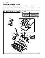
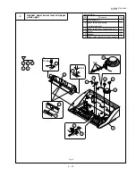
Operation panel
6
Parts list (Fig. 6)
Fig. 6
3 – 8
No.
Part name
Q’ty
No.
Part name
Q’ty
1
Operation panel unit
1
2
Screw (2
×
6)
3
3
Operation panel cable
1
4
Operation panel PWB
1
5
Document tray
1
6
Screw
1
7
Pinion gear
1
8
Hopper spring
1
9
Hopper guide, right
1
10
Hopper guide, left
1
11
Stop key
1
12
Start key
1
13
Direct key
1
14
12 key
1
15
Operation panel
1
Operation
panel PWB
LCD cable
LCD PWB
Confim of HOPPER GUIDE position
HOPPER
GUIDE (R)
HOPPER
GUIDE (L)
2
3
4
5
6
1
8
7
9
10 11
12
13
14
15
15
1
10
9
8
6
7
5
11
12
13
14
2
2
3
2
4
1
Rib
Rib
GAP 0
GAP 0
Summary of Contents for FO-375
Page 61: ...6 7 UX 108U 178U 188U FO 375U Control PWB parts layout Top side ...
Page 62: ...6 8 UX 108U 178U 188U FO 375U Control PWB parts layout Bottom side ...
Page 64: ...6 10 UX 108U 178U 188U FO 375U TEL LIU PWB parts layout ...
Page 66: ...6 12 UX 108U 178U 188U FO 375U Power supply PWB parts layout ...


