2 – 37
GX10i
CONFIDENTIAL
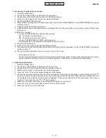
4. Procedures of white defect correction
1.
Attach the battery pack.
2.
Access the normal mode by holding down the power key.
3.
Connect the unit to the PC and send the [AT+XDIAG] command.
4.
Make sure the screen for the function test mode is displayed.
5.
Send the [LDDEVPRM] command.
6.
Block off light completely from the light sensor after receiving the [LDDEVPRMOK]. If the [LDDEVPRMNG] is received,
start from step 5.
7.
Transmit the [WHC01540160] command.
8.
6 digits will be received if the transmission is completed after 20 to 30 seconds. Be sure to continue to block off light during
this process.
<6 digits to be received>
• In case of [LDDEVPRMOK]: aaabbb will be received.
aaa: the number of white defects
bbb: the maximum level of dark current
• In case of [LDDEVPRMNG]: 000000 will be received.
This indicates light was not blocked completely. Go back to step 7.
9.
Send the [WH] command.
10. If [OK] is received, send the AT [SVDEVPRM] command.
11. After receiving the [SVDEVPRMOK], block off light completely from the light sensor. If the [SVDEVPRME1] is received,
go back to step 10.
12. Remove the Data cable from the unit. Press the “Power” key to exit.
* White defect correction
White defects indicate pixel defects in the image detected by the light sensor. These appear as white spots even when
light is completely blocked off (even on a black background). White defect correction solves this problem.
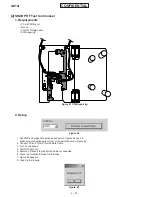
5. Optical axis adjustment
1.
Attach the battery pack.
2.
Access the normal mode by holding down the “Power” key.
3.
Connect the unit to the PC and send the [AT+XDIAG] command.
4.
Make sure the screen for the function test mode is displayed.
5.
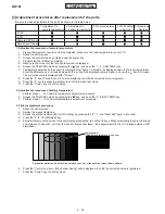
Press the “6” key. The camera image will appear on the display.
6.
Set your face in the center of the camera mirror and press the “Centre” key (for shooting). Correct the image with the “ ”
key if it is on the center right, and use the “ ” key if it is on the center left. Press the “Right Soft” key. [Param Save OK.]
will be displayed to notify the corrected value is registered. The screen is returned to the shooting screen. The image is
moved by 2 dots each time the “ ” or “ ” key is pressed.
7.
Make sure the image is set in the center after performing step 6 several times.
8.
Press the “0” key to access the initial screen of the function test mode.
9.
Press the “Power” key to exit this mode.


