2 – 65
GX10i
CONFIDENTIAL
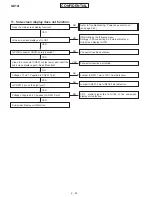
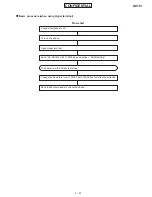
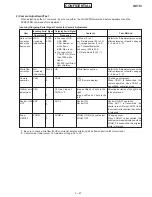
SRAM to
FROM
saving
POWER OFF
SVDEVPRM
PWRDOWN
None
None
SVDEVPRM OK
SVDEVPRM E1
None
After adjustment, adjusted values in
SRAM are saved to FROM.
POWER OFF when PWRDOWN is
transmitted.
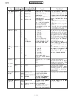
Item
Incoming Serial Signal Outgoing Serial Signal
Contents
Test Method
Command
n
Response
SRAM to FROM saving.
Garbled SRAM (No saving).*6
POWER OFF
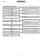
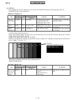
*1: The LED test is also available in the manual test mode F45.
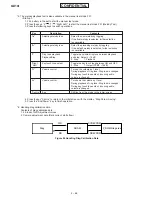
<Startup>
1. Fit a battery in the set to start the manual test mode.
2. Press the keys “4”
“5”
“Right Soft” to start the manual test mode F45 (LED Setting).
3. Press the following keys for ON/OFF operation.
“0”
OFF
All switches OFF
“1”
Charge LED ON/OFF
Charge LED (LED101: RED)
“2”
Incoming call LED ON/OFF
MA2 LED (LED101: GREEN)
“3”
Key LED ON/OFF
Key LED (LED302 to LED309: GREEN)
“4”
Back light ON/OFF
LCD Back light (Back light FPC: WHITE)
“5”
Test LED ON/OFF
Test LED (Not mount)
“6”
Sub back light ON/OFF
Sub Back light (LED001: WHITE)
“Centre”
End
Shifting from this mode to the initial screen
Key
Description
Contents
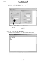
4. Press the key “Centre” to return to the initial screen with the display, “Diag Param Saving”.
5. Press the “End/Power” key to finish operation.
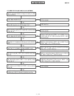
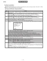
*2: YY=00: Year of 2000
RTC writing is also available in the manual test mode F40.
<Startup>
1. Fit a battery in the set to start the manual test mode.
2. Press the keys, “4”
“0”
“Right Soft”, to start the manual test mode F40 (Rtc Setting).
3. Press the following keys to set time of day. (For determination, press the key “Right Soft”.)
1: Year 2: Month 3: Day 4: Hours 5: Minutes 6: Seconds
4. Every time the key “Left Soft” is pressed, time of day is displayed in a moment.
5. Press the key “Centre” to return to the initial screen with the display, “Diag Param Saving”.
6. Press the “End/Power” key to finish operation.
*3: Only when performing the TMPAD4 command or turning power OFF/ON, A/D adjusted values are reflected in temperature.
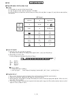
*4: The IrDA test is also available in the manual test mode F13.
<Startup in the jig mode>
Provide a set other than the tested set, which has been confirmed to operate normally. Use this set as the IrDA receiver.
1. Fit a battery in the set to start the manual test mode.
2. Press the keys, “1”
“3”
“Right Soft” to start the manual test mode F13 (IrDA Test).
3. Press the key “Left Soft” (S1: Test Device Mode).
* The infinite loop mode for the IrDA data stand-by is started. After finishing the test, remove the battery.
<Startup in the test mode>
Data are transmitted/received by using the tested set.
1. Fit a battery in the set to start the manual test mode.
2. Press the keys, “1”
“3”
“Right Soft”, to start the manual test mode F13 (IrDA Test).
3. Direct the IrDA window of the tested set to that of the jig set.
4. Press the key “0” (0: Check IrDA) to transmit “A5” data automatically.
5. When “OK Data: 5A” is displayed, transmitting/receiving is normally completed. When “NG Data: **” is displayed,
transmitting/receiving is abnormally ended.
6. Press the key “Centre” to return to the initial screen with the display, “Diag Param Saving”.
7. Press the “End/Power” key to finish operation.
Every time a key is
pressed, the
operation, “OFF
Brightness 1
2
3
4
standby
light”, is repeated.


