GX10i
CONFIDENTIAL
3 – 2
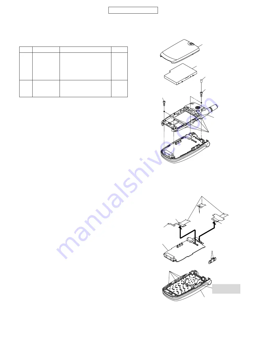
(B3) x 4
Key-PWB-B
(B1) x 1
(B2) x 2
(B2) x 1
(B2) x 2
(B1) x 1
Back Cabinet A'ssy, Display
Relay FPC
Electrostatic
plate (Inside) *
Figure 4
STEP
REMOVAL
PROCEDURE
FIGURE
1
Back Cabinet
1.Battery Cover .......... (A1)x1
3
Assembly,
2.Li-Ion Battery .......... (A2)x1
Key
3.Screw Cover ........... (A3)x2
4.Screw ...................... (A4)x4
5.Hook ........................ (A5)x4
2
Key PWB-B
1.Socket ..................... (B1)x2
4
2.Solder ...................... (B2)x5
3.Hook ........................ (B3)x4
[2] Disassembly and reassembly
Back Cabinet
Ass'y, Key
(A1) x 1
(A2) x 1
(A4) x 2
ø1.7 x 5 mm
(A4) x 2
ø1.7 x 5 mm
(A3) x 2
(A5) x 4
Figure 3
• To reassemble, follow the reverse procedure.
* Be careful not to deform the electrostatic plate
(PSLDC3348AFZZ) used to eliminate static
electricity when installing/removing the key PWB.


