background image

9

1

7

6

5

4

3

2

1

9

2011 January 27

HT-SB600

E-1

NOTE

This equipment has been tested and found to comply with
the limits for a Class B digital device, pursuant to Part 15
of the FCC Rules. These limits are designed to provide
reasonable protection against harmful interference in a
residential installation. This equipment generates, uses,
and can radiate radio frequency energy and, if not installed
and used in accordance with the instructions, may cause
harmful interference to radio communications. However,
there is no guarantee that interference will not occur in a
particular installation. If this equipment does cause
harmful interference to radio or television reception, which
can be determined by turning the equipment off and on,
the user is encouraged to try to correct the interference by
one or more of the following measures:

Reorient or relocate the receiving antenna.

Increase the separation between the equipment and
receiver.

Connect the equipment into an outlet on a circuit
different from that to which the receiver is connected.

Consult the dealer or an experienced radio/TV
technician for help.

WARNING

FCC Regulations state that any unauthorized changes or
modifications to this equipment not expressly approved by
the manufacturer could void the user’s authority to operate
this equipment.

Electricity is used to perform many useful functions, but it
can also cause personal injuries and property damage if
improperly handled. This product has been engineered
and manufactured with the highest priority on safety.
However, improper use can result in electric shock and/or
fire. In order to prevent potential danger, please observe
the following instructions when installing, operating and
cleaning the product. To ensure your safety and prolong
the service life of this product, please read the following
precautions carefully before use.
1) Read these instructions.
2) Keep these instructions.
3) Heed all warnings.
4) Follow all instructions.
5) Do not use this apparatus near water.
6) Clean only with dry cloth.
7) Do not block any ventilation openings. Install in

accordance with the manufacturer’s instructions.

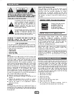
Special Notes

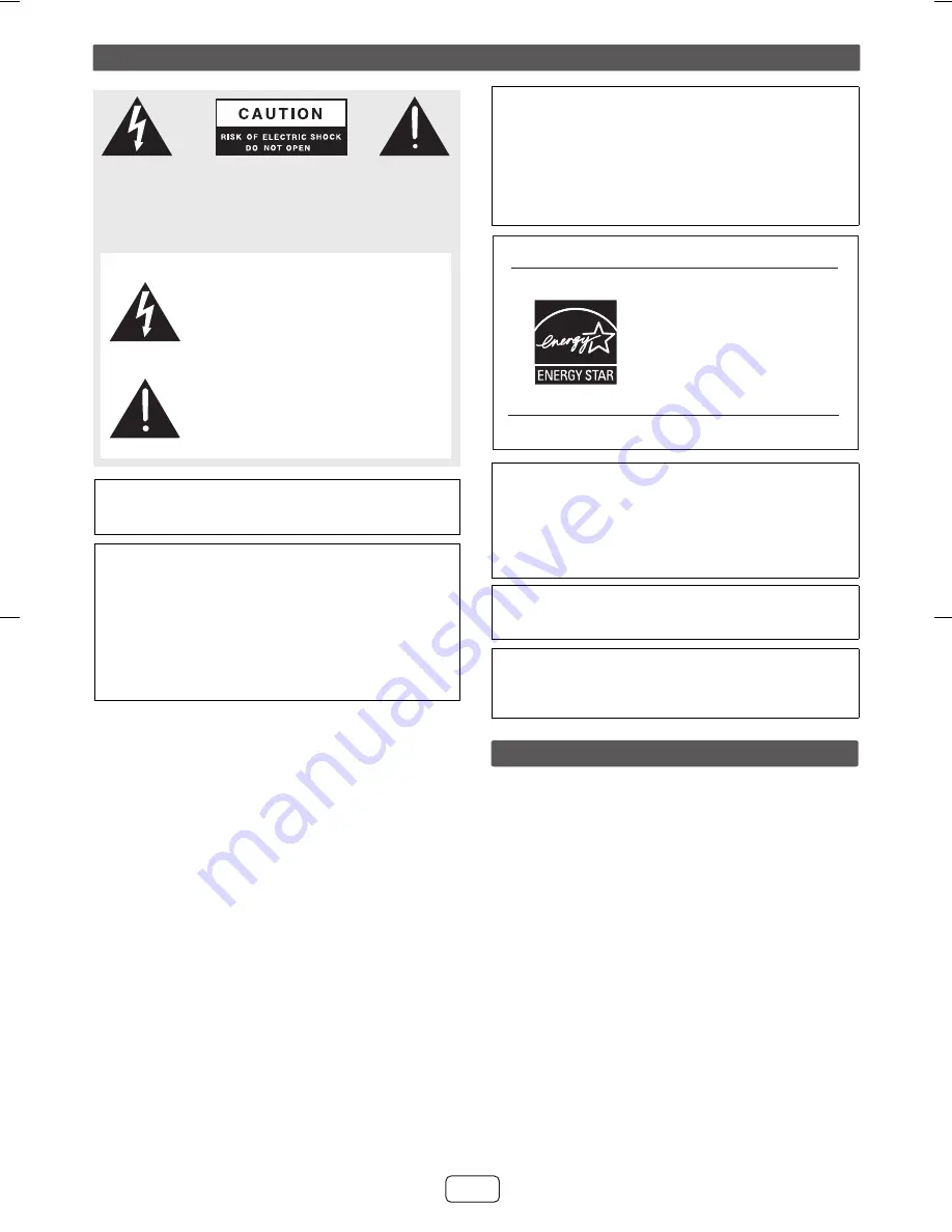
CAUTION: TO REDUCE THE RISK OF ELECTRIC
SHOCK, DO NOT REMOVE COVER (OR BACK).
NO USER-SERVICEABLE PARTS INSIDE. REFER
SERVICING TO QUALIFIED SERVICE PERSONNEL.

Explanation of Graphical Symbols:

The lightning flash with arrowhead symbol,
within an equilateral triangle, is intended to
alert the user to the presence of
uninsulated “dangerous voltage” within the
product’s enclosure that may be of
sufficient magnitude to constitute a risk of
electric shock to persons.

The exclamation point within an equilateral
triangle is intended to alert the user to the
presence of important operating and
maintenance (servicing) instructions in the
literature accompanying the appliance.

WARNING: TO REDUCE THE RISK OF FIRE OR
ELECTRIC SHOCK, DO NOT EXPOSE THIS
APPLIANCE TO RAIN OR MOISTURE.

FOR YOUR RECORDS

For your assistance in reporting this unit in case of loss
or theft, please record below the model number and
serial number which are located on the rear of the unit.
Please retain this information.

Model number         

........................................................

Serial number          

........................................................

Date of purchase     

........................................................

Place of purchase   

........................................................

Note to CATV system installer:

This reminder is provided to call the CATV system
installer’s attention to Article 820 of the National
Electrical Code that provides guidelines for proper
grounding and, in particular, specifies that the cable
ground shall be connected to the grounding system of
the building, as close to the point of cable entry as
practical.

Manufactured under license under U.S. Patent
#: 5,451,942; 5,956,674; 5,974,380; 5,978,762;
6,487,535 & other U.S. and worldwide patents issued &
pending. DTS and the Symbol are registered trademarks
& DTS Digital Surround and  the DTS logos are
trademarks of DTS, Inc. Product includes software. 
© DTS, Inc. All Rights Reserved.

Manufactured under license from Dolby Laboratories.
Dolby, Pro Logic, and the double-D symbol are
trademarks of Dolby Laboratories.

HDMI, the HDMI Logo, and High-Definition Multimedia
Interface are trademarks or registered trademarks of
HDMI Licensing LLC in the United States and other
countries.

ENERGY 

S

TAR

®

  Program Information

Product

s

 that have earned

the ENERGY 

S

TAR

®

 are

de

s

igned to protect the

environment through

s

uperior energy efficiency.

ENERGY 

S

TAR

®

 i

s

 a U.

S

. regi

s

tered mark.

Important Safety Instructions

Summary of Contents for HT-SB600

Page 1: ...ce from this product please read this manual carefully It will guide you in operating your SHARP product TINSEA352AWZZ Printed in Malaysia 10K R KI 1 MODEL HT SB600 SOUND BAR SYSTEM ENGLISH HT SB600 Sound Bar system consisting of HT SB600 main unit CP SB600 sound bar and CP SW600 subwoofer Please confirm that only the following accessories are included AM Loop Antenna QANTLA004AWZZ Remote Control ...

Page 2: ...urer s instructions Special Notes CAUTION TO REDUCE THE RISK OF ELECTRIC SHOCK DO NOT REMOVE COVER OR BACK NO USER SERVICEABLE PARTS INSIDE REFER SERVICING TO QUALIFIED SERVICE PERSONNEL Explanation of Graphical Symbols The lightning flash with arrowhead symbol within an equilateral triangle is intended to alert the user to the presence of uninsulated dangerous voltage within the product s enclosu...

Page 3: ... Adjust only those controls that are covered by the operating instructions as an improper adjustment of other controls may result in damage and will often require extensive work by a qualified technician to restore the product to its normal operation e If the product has been dropped or damaged in any way and f When the product exhibits a distinct change in performance this indicates a need for se...

Page 4: ...ive warranties granted by Sharp and shall be the sole and exclusive remedy available to the purchaser Correction of defects in the manner and for the period of time described herein shall constitute complete fulfillment of all liabilities and responsibilities of Sharp to the purchaser with respect to the Product and shall constitute full satisfaction of all claims whether based on contract neglige...

Page 5: ... same as that specified on this unit Using this product with a higher voltage other than that which is specified is dangerous and may result in a fire or other type of accident causing damage SHARP will not be held responsible for any damage resulting from use of this unit with a voltage other than that which is specified The sound level at a given volume setting depends on speaker efficiency loca...

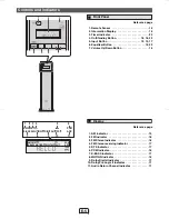
Page 6: ...2 FM Indicator 18 3 FM Stereo Indicator 18 4 FM Stereo receiving Indicator 17 5 DTS Indicator 17 6 PCM Indicator 18 7 X BASS Indicator 17 8 MUTING Indicator 16 9 Dolby Digital Indicator 17 10 Dolby Pro Logic II Indicator 17 11 Audio Return Channel Indicator 17 Controls and indicators 1 2 3 4 5 6 7 Front Panel AM X BASS FMST DIGITAL ARC PCM PL MUTING 1 2 3 4 5 6 7 8 9 10 11 AM X BASS FMST DIGITAL A...

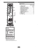
Page 7: ...Front Speaker Terminal 11 7 Center Speaker Terminal 11 8 Subwoofer Terminal 11 9 HDMI TV ARC Output Jack 12 10 HDMI input Jack 12 11 Cooling Fan 4 12 AC Power Cord 11 Controls and indicators continued 9 10 11 6 7 8 2 3 4 1 5 12 The spec label The spec label illustration may be different from the actual label used Label is located at the bottom of the unit Rear Panel ...

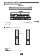
Page 8: ...5 Right Front Speaker terminal 11 6 Center Speaker terminal 11 7 Left Front Speaker terminal 11 Reference page 1 Bass Reflect Duct 2 Woofer 3 Speaker Terminals 11 Controls and indicators continued Sound Bar 1 2 2 3 4 2 7 5 6 FRONT VIEW REAR VIEW Subwoofer 3 1 2 SUBWOOFER SYSTEM FRONT VIEW REAR VIEW ...

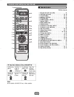
Page 9: ...Treble Button 17 22 Center Speaker Level Up Button 17 23 Center Speaker Level Down Button 17 24 Volume Up Button 16 17 25 Preset Down Button 18 19 Note Some models of SHARP TV may not be operable Controls and indicators continued ARC TV CLOCK DIMMER TUNING TUNER BAND EQUALIZER X BASS CHANNEL VOL VOL VOL INPUT TV BASS TREBLE MUTE TIMER LINE DIGITAL SUBWOOFER LEVEL PRESET PRESET CENTER LEVEL 1 2 1 2...

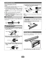
Page 10: ...ot supplied into each hole as shown and tie the safety wires to the LCD TV stand Speaker preparation To mount the speaker on the wall 1 Fix the pattern paper to the wall in horizontal position as below 2 Make a hole on the wall following the screw point marks on the pattern paper by using a drill 3 Fix a wall mount plug not supplied into the hole using a hammer until it is flush with the wall surf...

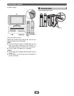
Page 11: ...you like However it is recommended to place it as close to the TV as possible The front panel of the speaker is not removable Caution Do not change the installation direction when the unit is turned on Do not stand or sit on the main unit and speakers as you may be injured Placing the system SUBWOOFER SYSTEM TV VCR DVD player Main unit Subwoofer Place the stand as shown Placing the stand SUBWOOFE ...

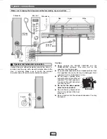
Page 12: ...d Subwoofer connection INPUT INPUT Purple Never mistake the FRONT CENTER and the SUBWOOFER terminals The main unit or the speakers may be damaged If you use other speakers with an impedance lower than that specified the main unit may be damaged Front speakers 4 ohms Subwoofer 4 ohms Do not make a mistake when connecting the right and the left speakers The right speaker is the one on the right side...

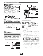
Page 13: ...e sure to use High Speed HDMI cables and put on the 3D glasses otherwise 3D images may not be viewed properly System connections continued Supplied FM antenna Connect the FM antenna wire to the FM 75 OHMS jack and position the FM antenna wire in the direction where the strongest signal can be received Supplied AM loop antenna Connect the AM loop antenna to the AM and GND Ground terminals Position ...

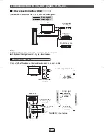
Page 14: ...ctions to TVs DVD players VCRs etc Other connection without HDMI DVD Blu ray Disc Player VCR Game console Digital tuner etc TV Audio signal Video signal Connecting a TV etc TV Audio cable commercially available To LINE IN 2 input terminals To LINE IN 1 input terminal Optical digital audio cable commercially available Main unit Audio signal Audio signal To optical digital audio output terminal To a...

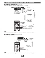
Page 15: ...player etc Blu Ray DVD Player Digital tuner To audio output terminals Audio cable commercially available To optical digital audio output terminal To LINE IN 2 input terminals To DIGITAL IN 2 coaxial terminal input Optical digital audio cable commercially available Main unit Audio signal Audio signal To the TV video To DIGITAL IN 1 optical input terminal To coaxial digital audio output terminal Coa...

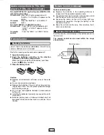
Page 16: ...ote control away from moisture heat shock and vibrations Point the remote control directly at the remote sensor on the main unit The remote control can be used within the range shown below To select DIGITAL IN 1 optical input or DIGITAL IN 2 coaxial input function On main unit Press INPUT button repeatedly until DIGITAL 1 or DIGITAL 2 appears on the display On remote control Press the DIGITAL 1 or...

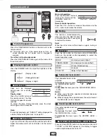
Page 17: ...ntrol Clock can be displayed during power On or standby mode Display clock Press the CLOCK button on the remote control The time display will appear for about 5 seconds To cancel the time display manually press the clock button again within 5 seconds ARC TV CLOCK DIMMER TUNING TUNER BAND EQUALIZER X BASS VOL VOL BASS TREBLE MUTE TIMER LINE DIGITAL SUBWOOFER LEVEL PRESET CENTER LEVEL 1 2 1 2 1 2 3 ...

Page 18: ...tor will appear To cancel the extra bass mode press the X BASS or BASS TREBLE button On the main unit When pressing the INPUT button the input source will change Press the INPUT button repeatedly to select desired input source On remote control Press the LINE 1 or 2 button to select LINE IN 1 input or LINE IN 2 input Press the DIGITAL 1 or 2 button to select DIGITAL IN 1 input or DIGITAL IN 2 inpu...

Page 19: ...he desired frequency band FM Stereo FM Mono AM 3 Press the TUNING or button to tune in to the desired station Manual tuning Press the TUNING or button as many times as required to tune in to the desired station Auto tuning When the TUNING or button is pressed for more than 0 5 seconds scanning will start automatically and the tuner will stop at the first receivable broadcast station Listening to t...

Page 20: ...advance the time by 1 hour Hold it down to advance continuously When the 12 hour display is selected AM will change automatically to PM 4 Press the or button to adjust the minutes and then press the ENTER button Press the or button once to advance the time by 1 minute Hold it down to advance continuously 5 minutes interval The hour will not advance even if minutes advance from 59 to 00 The clock s...

Page 21: ...n the timer playback stand by mode The same operation can be performed in the following procedure without turning the power on 1 Press the TIMER button TIMEROFF will appear 2 Within 10 seconds press the ENTER button Timer playback will be canceled the contents of the setting will not be canceled Reusing the timer Using the same setting The timer setting will be memorized once it is entered To reus...

Page 22: ...bwoofer level set to the minimum or maximum level Power turns off suddenly Is the HDMI cable connected correctly Connect the HDMI cable correctly and then perform the reset procedure Noise is heard during playback Move the speaker away from any computers or mobile phones When a button is pressed the unit does not respond Set the unit to the stand by mode and then turn it back on The power is not t...

Page 23: ...ions properly the following messages are displayed on the unit Should the same message appear even if the speaker is unplugged and plugged in or is set to the stand by mode and on again contact your local dealer where you purchased the unit Troubleshooting chart continued Factory reset clearing all memory Maintenance Cleaning the cabinet Display Meaning Malfunction of the surround circuit Place th...

Page 24: ...nnel into 4 ohms at 120 Hz to 20 kHz 1 total harmonic distortion Subwoofer Minimum 80 watts per channel into 4 ohms at 100 Hz 1 total harmonic distortion Output terminal HDMI output audio video support up to 1080p x 1 Input terminal Analog input LINE 1 Stereo mini jack Ø 3 5 mm 100 mV 47 kohms Analog input LINE 2 RCA type x 1pair L R 500 mV 47 kohms Coaxial digital input DIGITAL 2 RCA type x 1 Opt...

Reviews: