background image

InstallatIon Manual

b


drIll pIlot holes and Fasten braCket 

Drill a 

1

/

8

-inch pilot hole where screws are to be located. If bracket 

is to be mounted to the wall, drill pilot hole at an approximate 20 

degree downward angle. If bracket is to be mounted to masonry or 

ceramic floors, drill a 

5

/

32

-inch pilot hole 1 

3

/

4-

inches deep. The 

screws provided may be used in wood or concrete material. Use a 

5

/

16

-inch nut-driver or flat head screwdriver to secure the bracket 

in place.

c


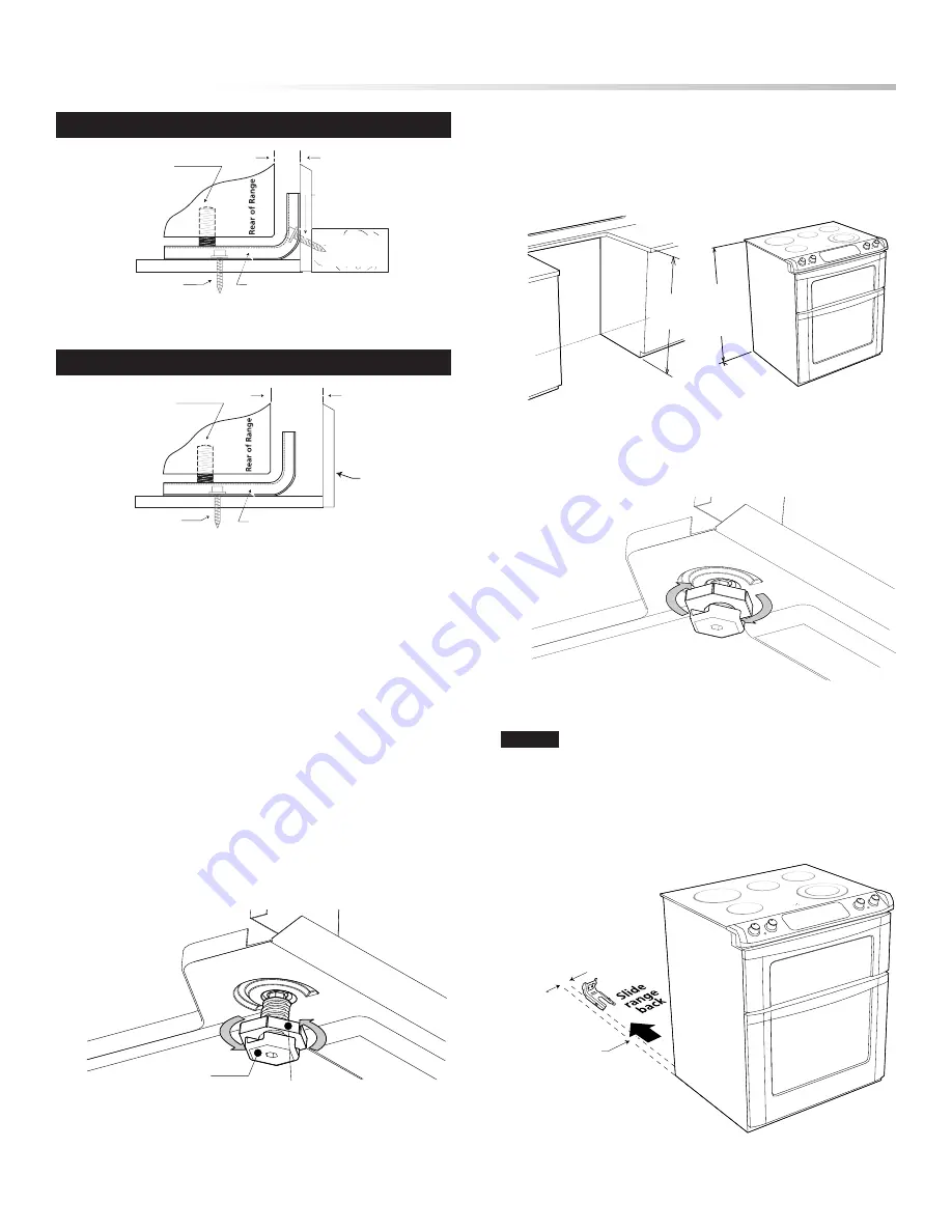
leVel and posItIon range 


•    Measure from the countertop to the floor height to determine 

the height that the back of the range needs to be set at.

  •  Loosen legs and lock nuts to set level of the range. (Note that 

the lock nuts are only on the rear feet). See Figure 16.

Figure 19

FASTEN BRACKET (WALL OR FLOOR MOUNTING)

FASTEN BRACKET (FLOOR MOUNTING ONLY)

floor mount

floor mount

Anti-Tip bracket

Anti-Tip bracket

wall

wall mount

wall plate

more than
11/4"

max 11/4"

leveling leg

leveling leg

Figure 14

Figure 15

Range Leg

Lock Nut

(Rear leg only)

Figure 16

  •   Adjust the back leveling legs with an adjustable wrench or pliers. 

Measure from the floor to the bottom of the cooktop glass (X) 

and adjust the legs to match the measurement (Y) taken from 

the cutout. See Figure 17.

(X")

floor to bottom

off cooktop

glass

(Y")

floor to top

of countertop

Figure 17

  •  After leveling, tighten the lock nuts on the rear to prevent the 

feet from turning when sliding into position. See Figure 18.

Figure 18

note:

 A minimum clearance of 1/8-inch is required between 

the bottom of the range and the leveling leg to allow room for the 

bracket. Use a level to check your adjustments. Plug range into 

properly prepared electrical receptacle or if hard wired, check that 

it was completed properly. Check floor condition for evenness and 

stability. Slide range back into position. See Figure 19.

Range Slide

1 5/8" to edge

of bracket

Summary of Contents for Insight Electric Rang

Page 1: ... CONSIDERATIONS do not install a appliance in any combustible cabinetry which is not in accord with the stated clearances and dimensions on page 2 See Figures 1 and 2 Range Measurements 2 Clearances and Dimensions 2 Important Notes 3 Unpacking and examining your range 3 Important Safety Instructions 3 Electrical connections 4 6 Model and Serial number Location 4 Anti Tip 6 8 Care Cleaning and Main...

Page 2: ...9 msg sheet steel 0 015 inch stainless steel 0 024 inch aluminum or 0 020 inch copper Note that the gray shaded area on Figure 2 indicates the location for the electrical receptacle connection Contact surface must be solid and level Pay special attention to the floor Be sure it is solid enough for the weight of the range Check that the floor covering is smooth and flat and that it adheres to the s...

Page 3: ...ion Never use the range for warming or heating the room Do not store or use gasoline or other flammable vapors and liquids near this or any other range Explosions or fires could result Reset all controls to the off position after using a programmable timing operation When using the Self Clean Feature Remove broiler pan oven racks food and other utensils before self cleaning the oven Wipe up excess...

Page 4: ...ed at an appliance store For mobile homes new installations recreational vehicles or areas where local codes do not permit grounding through neutral a 4 con ductor power supply cord kit rated at 240 volts or 208 volts minimum 50 amperes and marked for use with ranges should be used Terminals on end of wires must be either closed loop or open end spade lugs with upturned ends Cord must have strain ...

Page 5: ...ource 4 Make sure all connections are tightened securely and replace the rear access cover and secure with screw See Figure 7 3 4 WIRE PERMANENT WIRE CONNECTIONS 3 wire permanent connection follow steps 1 2 and 5 below 4 wire permanent connection follow all steps below Before wiring the range review the suggested power source location drawings in Figure 2 If connecting to a 4 wire electrical syste...

Page 6: ...e wall or no further than 1 1 4 inches from wall when installed you may use the wall or floor mount method See Figure 14 If molding is installed and does not allow the bracket to fit flush against the wall remove molding or mount bracket to the floor For wall mount locate the bracket by placing the back edge of the template against the rear wall and the side edge of template on the mark made refer...

Page 7: ...mount floor mount Anti Tip bracket Anti Tip bracket wall wall mount wall plate more than 11 4 max 11 4 leveling leg leveling leg Figure 14 Figure 15 Range Leg Lock Nut Rear leg only Figure 16 Adjust the back leveling legs with an adjustable wrench or pliers Measure from the floor to the bottom of the cooktop glass X and adjust the legs to match the measurement Y taken from the cutout See Figure 17...

Page 8: ...ons in your Operation Manual It may save you time and expense The list includes common occurrences that are not the result of defective workmanship or materials in this range Refer to your Operation Manual for our service address Sharp s toll free telephone number is 1 800 BE SHARP 1 800 237 4277 Please call or write if you have inquiries about your range product and or need to order parts NOTE Pl...

Reviews: