background image


SOLAR POWER CONDITIONER 


Service Manual 


Summary of Contents for JH-1600E

Page 1: ...SOLAR POWER CONDITIONER Service Manual ...

Page 2: ...Checking and Changing Parameter of Operating Condition 13 4 Clearing Error 16 5 Error Code and Service 17 Replacing Fuse 28 1 Detaching Wiring Box 28 2 Checking DC Fuse 28 3 Checking AC Fuse 28 4 Replacing AC or DC Fuse 29 Replacing Unit 30 1 Detaching Wiring Box 30 2 Remove AC DC and Communication Cables 30 3 Detach Two Screws on the Bottom of the Unit 30 4 Remove the Unit from the Wall Mount Bra...

Page 3: ...uring the installation of the solar power conditioner To reduce the risk of electrical shock and to ensure the safe installation and operation of the solar power conditioner the following words appear throughout this manual to inform you or alert you something may cause dangerous situation or safety instructions must be followed ...

Page 4: ...module always supplies the DC voltage of 60V to 350V on daytime particularly sunny day Be careful when treating the cable from the PV module Otherwise it may cause an electrical shock Do not repair the solar power conditioner with wet hands Otherwise it may cause an electrical shock Make sure to be earthen if the solar power conditioner is repaired in wet place Otherwise it may cause an electrical...

Page 5: ...he connection status of crimping terminal are all appropriate Otherwise it may cause heat fire or an electrical shock If mounting structure or mounting components are deteriorated such as corroded replace them with new ones Otherwise it may fall down and cause injury Be sure to check grounding status and set it appropriately Otherwise it may cause an electrical shock Never apply the voltage of mor...

Page 6: ... 3 DC Wiring cable Connect PV array to DC breaker PV array A number of PV modules connected together in a single mounting structure 4 DC breaker Isolate the PV array from solar power conditioner 5 Solar power conditioner The solar power conditioner converts DC power generated by PV array into AC power and automatically controls the operation of system 6 AC breaker Isolate AC power from solar power...

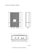
Page 7: ...2 Overview of solar power conditioner Unit mm Fig1 Dimension of solar power conditioner 6 ...

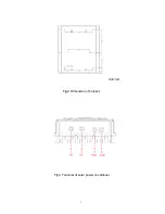
Page 8: ...Unit mm Fig2 Dimension of bracket Fig3 Terminal of solar power conditioner 7 ...

Page 9: ...Wiring box IP55 Dimensions without wall mount H W D mm 440 348 141 mm Dimensions with wall mount H W D mm 440 348 153 mm Shipping dimension H W D mm 515 450 290 mm Inverter weight 13 kg Shipping weight 18 kg Input connection From 16 to 10 AWG Output connection From 16 to 10 AWG ...

Page 10: ...nput 200 320 VDC Power Factor 0 95 more than rated output power1 8 Total Current Harmonic Distortion 5 Operating temperature range 20 60 derating at 40 60 Dimensions without wall mount 440 348 141 mm Dimensions with wall mount 440 348 153 mm inverter weight 13 kg Shipping weight 18 kg Main Circuit System Solar power conditioner system Voltage stiff current control system Switching system PWM pulse...

Page 11: ...ient temperature Solar Power Conditioner 20 C to 60 C 4 F to 140 F Higher than the altitude of about 2 000 m above sea level Prone to damage by sea water Close to corrosive gas or liquid for example locations where chemicals are processed feedlots or poultry Avoid the unit to exposed to direct sunlight Prone to flooding or high levels of snow pack High humidity Condensation Exposure to steam vapor...

Page 12: ...ioner is powered on Indicator is displayed on the solar power conditioner display The solar power conditioner is not powered but connected to the utility B Press SELECT button The display panel displays the accumulated daily power with displaying Wh D C Press SELECT button again The display panel displays the accumulated total power with displaying kWh No pressing any button for 10 seconds returns...

Page 13: ...system Check DC disconnect device Check PV string Voltage Repair DC disconnect device NO YES Check AC disconnect device NO YES NO YES Check utility grid voltage Voltage OK 210 250Vac Ask about normal utility to power company YES NO Check Solar Power Conditioner Repair solar power conditioner YES NO Operation OK Connection OK Voltage OK 60 120Vdc Repair PV module Repair AC disconnect device Connect...

Page 14: ...rameters of solar power conditioner 1 Turn on the PV string 2 Take off the cover of wiring box 3 Press ENT button for 5 second to display OFF 4 Parameter number and its value will be displayed in the display panel by press SEL and ENT button 5 After finishing confirmation of parameter value and setting press ENT button Display shows OFF 6 Setting parameter flow chart attaches below 7 Attach the co...

Page 15: ... List Please refer to the software Setting SEL SEL SEL Parameters Setting Changed MPPT mode Fault mode Night time mode SEL Standby mode SEL Error List ENT ENT ENT ENT ENT ENT ENT SEL SEL ENT SEL SEL SEL SEL SEL SEL SEL SEL SEL SEL SEL ENT ENT SEL SEL SEL ENT ENT SEL SEL ENT Day Power List ENT ENT ENT ENT ENT SEL ...

Page 16: ...bnormal trip time sec Setting trip time when over and under frequency protection is triggered 7 Recover timer Setting solar power conditioner recovery time when error occurrence 8 RJ 45 ID Setting RJ 45 ID number 9 Operation frequency Setting utility frequency Table2 Setting value and parameter The shadow value is default setting Item Function Parameters 1 Utility over voltage Vac 250 255 260 2 Ut...

Page 17: ...SL Step6 Press ENT button the display panel show r_EL Press ENT button repeat step5 and step6 can reset error list Step7 Press SEL button the display panel show r_IP Press ENT button repeat step5 step7 can reset integrated power Step8 Press SEL button until OFF is displayed Step9 Press ENT button 5 second the solar power conditioner will start operation again SEL button ENT button 4 2 Clearing d x...

Page 18: ...ditioner If L N is 255V in case of preset value or more it is in abnormal condition Case 1 Action Change the parameter setting to a higher level and make sure the utility voltage is low enough than setting value Cause Output impedance is too large to make the output terminal voltage is over setting value Check Check the impedance between inverter and the grid and the cable loss can not be over 1 o...

Page 19: ...g Check Check wiring and terminal of the CNW7 in the wiring box Case 4 Action Re wiring on the terminal of CNW7 Cause AC fuse is blown out Check Check the resistance of fuse FUW2 with meter in the wiring box Case 5 Action Replace the fuse FUW2 inside the wiring box Cause Defect grid voltage detector circuitry Check Check the voltage of receiving utility voltage if its voltage is large than setting...

Page 20: ... Check If the error message F 03 appears frequently after restarting the solar power conditioner the frequency detecting circuit on the control circuit is in abnormal condition Case 2 Action Replace a new solar power conditioner Error code F 06 Recovery method B Description Anti islanding protection frequency over Protection level Activation time Cause Power failure of the utility grid Check The s...

Page 21: ... If the error message F 08 appears frequently after restarting the solar power conditioner the polarity detecting circuit on the control circuit is in abnormal condition Case 1 Action Replace a new solar power conditioner Error code F 09 Recovery method B Description Frequency abnormal Protection level Wrong utility frequency setting 50Hz 60Hz Activation time Cause Wrong utility frequency setting ...

Page 22: ...e the number of series connection of PV modules in necessary Cause PV array voltage detector circuit is failed Check Check the voltage of all input terminal of the solar power conditioner is correct of not Case 2 Action If the error message P 11 appears frequently after confirming the PV array voltage Replace a new solar power conditioner Error code E 15 d 15 Recovery method C Description Relay st...

Page 23: ...ars frequently after restarting the solar power conditioner the communication circuit is in abnormal condition If this error occurs four times successively d 16 is displayed and the solar power conditioner stops Case 3 Action Replace a new solar power conditioner Error code E 17 d 17 Recovery method C Description Aux power abnormal Protection level Activation time Cause Noise interference Check Co...

Page 24: ...r is damage Case 2 Action Replace a new solar power conditioner Error code d 20 Recovery method D Description Temperature sensor broken Protection level Activation time Cause CNW5 CNW6 disconnect Check Confirm that CNW5 and CNW6 are connecting correctly or not If loosely connect it and restart solar power conditioner Case 1 Action Connect CNW5 and CNW6 tightly Cause Thermal fuse broken Check Measu...

Page 25: ...ion time Cause Caused by load used near the solar power conditioner DC 75mA is included with the output of the solar power conditioner Check Confirm that the solar power conditioner and restarts Case 1 Action Cause DC offset detector circuit is abnormal Check If the error message E 22 appears frequently after restart the solar power conditioner the solar power conditioner is in abnormal condition ...

Page 26: ...ower conditioner the solar power conditioner is in abnormal condition If this error occurs four times successively d 23 is displayed and the solar power conditioner stops Case 4 Action Replace a new solar power conditioner Error code E 26 d 26 Recovery method C Description DC DC converter abnormal Protection level Activation time Cause The setting of gain parameters is wrong Check Check the voltag...

Page 27: ...imes successively d 27 is displayed and the solar power conditioner stops Case 2 Action Replace a new solar power conditioner Error code E 28 Recovery method C Description DC bus voltage abnormal Protection level Activation time Cause Noise interference Check Confirm that the AC and PV terminal noise If the noise is large beyond acceptable Case 1 Action Turn off solar power conditioner immediately...

Page 28: ...rmal Protection level Activation time Cause EEPROM failed Check If the error message D 40 appears frequently after confirming the PV array voltage The solar power conditioner is damaged Case 1 Action Replace a new display board ...

Page 29: ...e conditioner II Check resistance of DC fuse FUW1 located in the wiring box board by multi meter If the resistance is huge DC fuse blew out In this case other components may have defect to cause fuse blow out The solar power conditioner is required to be checked in the factory 3 Checking AC Fuse I Perform 1 Detaching Wiring Box and remove the wiring box cover of the conditioner II Check resistance...

Page 30: ...ox and remove the wiring box cover of the conditioner II Remove the AC fuse from the holder III Remove the DC fuse from the holder IV Insert a new AC fuse FUW2 into the holder little fuse 20A 250V V Insert a new DC fuse FUW1 into the holder little fuse 15A 600V ...

Page 31: ...se an electrical shock II Confirm the DC and AC power are turned off and remove four screws located on the wiring box cover and take off the wiring box cover 2 Remove AC DC and Communication cables I Perform 1 Detaching Wiring Box and detach the all cables connected to the solar power conditioner 30 3 Detach two screws on the bottom of the unit AC cable Communication cable DC cable ...

Page 32: ...4 Remove the unit from the wall mount bracket 31 ...

Page 33: ...oner display DC input voltage is more than 70V Error code F 01 displayed It is right because the AC power breaker is turned off No displayed The display of solar power conditioner or its cable fail 3 Checking contents of solar power conditioner display Check all parameters setting of solar power conditioner If OFF is displayed Press ENT button for more than 5 seconds in the wiring box and confirm ...

Page 34: ...o kill the spike voltage of inverter diodes for protection purpose 6 Inverter switch Using four MOSFETs as switch to adjust the polarity of AC voltage 7 AC EMI To prevent conduction noise out from AC cable 8 Control board To control all circuit operation under desire 9 Junction box wiring box Including AC terminal DC terminal AC fuse DC fuse and parameter setting button 10 Communication and displa...

Page 35: ...40102 DC fuse 1 3 9NK3071538194 Terminal block DC 1 4 9NK3071539594 Terminal block AC 1 5 9NK3262043000 Shock Hazard warning label 1 6 9NK3470343100 AC DC Gland 2 7 9NK3470343200 RJ45 Gland 2 8 9NK3312387700 Wiring box front cover 1 9 9NK3263048200 Label for wiring box front cover upper side 1 34 ...

Page 36: ...m Parts Code Description Quantity 10 9NK3103381000 Screw for wiring box front cover 4 11 9NK3105299000 Screw for main body 38 12 9NK3263876000 Rating label 1 13 9NK3262043100 Burn Hazard warning label 1 35 ...

Page 37: ... 103 9NK35009554XX Bag PE 1 104 9NK35188379XX Top end block EPE 1 Item Parts Code Description Quantity 105 9NK33123936XX Wall mounting bracket 1 106 9NK31033810XX Screw M 6 32 10 Fix unit to the bracket 2 107 9NK31090374XX Screw ψ5 5 1 8 80 Fix bracket to the wall 10 108 9NK50113648XX Installation Operation Manual 1 36 ...

Page 38: ...Packing instruction 37 ...

Page 39: ...38 ...

Reviews: