


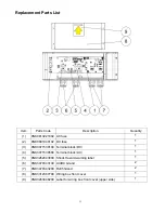


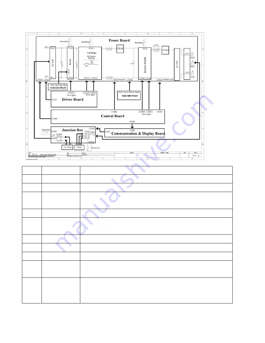
Circuit and electrical block diagram
Item Function
Description
1
DC EMI
To prevent conduction noise out from DC cable.
2
Boost
To regular DC voltage for inverter stage.
3
Full bridge
Using four MOSFETs as switch to inverter DC voltage to AC
voltage.
4 Driver
board
Generator driver signal of full bridge for MOSFETs.
5 Spike
killer
board
To kill the spike voltage of inverter diodes for protection purpose.
6
Inverter switch Using four MOSFETs as switch to adjust the polarity of AC voltage.
7
AC EMI
To prevent conduction noise out from AC cable.
8
Control board To control all circuit operation under desire.
9 Junction
box
(wiring box)
Including AC terminal, DC terminal, AC fuse, DC fuse, and
parameter setting button.
10 Communication
and display
board
1. As a communication bridge between control board and user
(through RJ-45 connector).
2 Display operation status and information.
33
Summary of Contents for JH-1600E
Page 1: ...SOLAR POWER CONDITIONER Service Manual ...
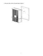
Page 7: ...2 Overview of solar power conditioner Unit mm Fig1 Dimension of solar power conditioner 6 ...
Page 8: ...Unit mm Fig2 Dimension of bracket Fig3 Terminal of solar power conditioner 7 ...
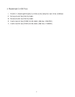
Page 32: ...4 Remove the unit from the wall mount bracket 31 ...
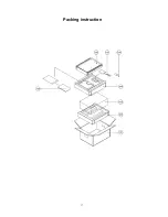
Page 38: ...Packing instruction 37 ...
Page 39: ...38 ...


