background image

LC-15PX1U

8

7

10

9

6

5

4

3

2

1

A

C

D

E

F

G

H

48

Ë

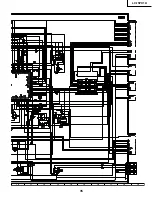
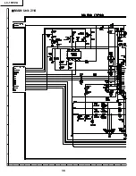
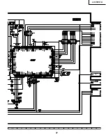
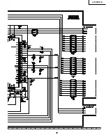
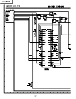
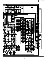
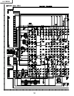
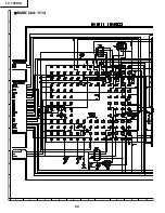
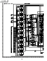
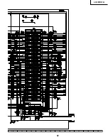
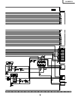
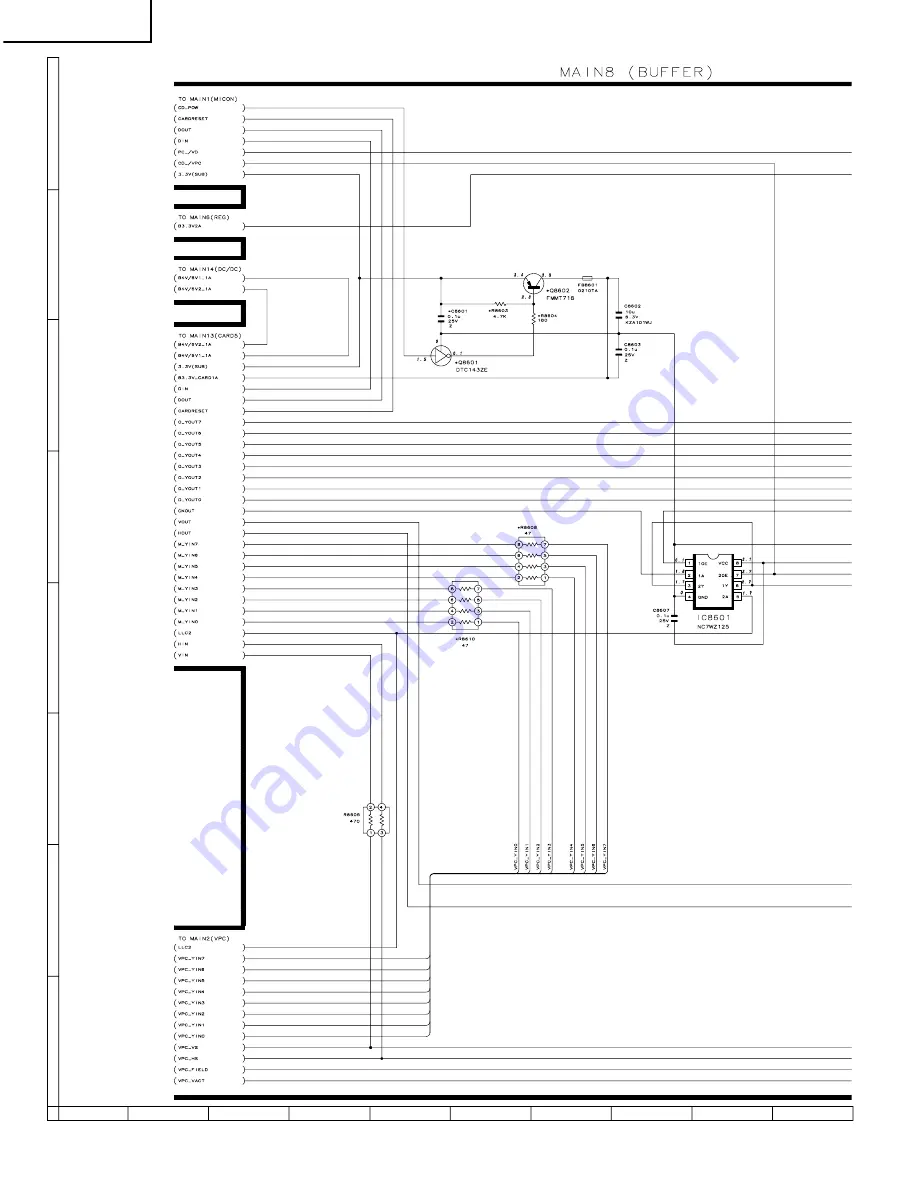
MAIN Unit-8/14

Summary of Contents for LC-15PX1U

Page 1: ...fter sales service only The contents are subject to change without notice LCD COLOR TELEVISION CONTENTS IMPORTANT SERVICE SAFETY PRECAUTION 2 SPECIFICATIONS 5 OPERATION MANUAL 6 DIMENSIONS 8 REMOVING OF MAJOR PARTS 9 ADJUSTING PROCEDURE OF EACH SECTION 14 TROUBLE SHOOTING TABLE 20 CHASSIS LAYOUT 26 BLOCK DIAGRAM 28 OVERALL WIRING DIAGRAM 30 DESCRIPTION OF SCHEMATIC DIAGRAM 32 SCHEMATIC DIAGRAM 33 ...

Page 2: ...ry recommended replacement parts shown in this service manual may create shock fire or other hazards WARNING 1 For continued safety no modification of any circuit should be attempted 2 Disconnect AC power before servicing BEFORE RETURNING THE RECEIVER Fire Shock Hazard Before returning the receiver to the user perform the following safety checks 1 Inspect all lead dress to make certain that leads ...

Page 3: ...utions incendies radiations X ou autres accidents AVERTISSEMENT 1 N entreprendre aucune modification de tout circuit C est dangereux 2 Débrancher le récepteur avant toute réparation VERIFICATIONS CONTRE L INCEN DIE ET LE CHOC ELECTRIQUE Avant de rendre le récepteur à l utilisateur effectuer les vérifications suivantes 1 Inspecter tous les faisceaux de câbles pour s assurer que les fils ne soient p...

Page 4: ... is higher than the conventional lead solder by 40 C and as it has poor solder wettability you may be apt to keep the soldering bit in contact with the PWB for extended period of time However Since the land may be peeled off or the maximum heat resistance temperature of parts may be exceeded remove the bit from the PWB as soon as you confirm the steady soldering condition Lead free solder contains...

Page 5: ...DIO IN OUT Antenna F Type Headphone Mini jack for stereo ø3 5 mm OSD language English Spanish French Power supply DC 12V AC 110 240V 50 60Hz AC adapter AC 110 125V AC cord Power consumption 49 W 0 4 W standby AC 120V 40 W DC 12V Weight 12 6 lbs 5 7 kg w o accessories Accessories Remote control Battery 2 Antenna cable AC adapter AC cord Cable holder Operation manual ËAs a part of policy of continuo...

Page 6: ...Please adjust the angle so that the display can be watched most comfortably MAIN POWER Upper control panel TV VIDEO MENU CH Channel VOL Volume Tilt the display by grabbing onto the carrying handle while securely holding down the stand with your hand How to adjust the angle Listening with Headphones Plug the headphone mini plug into the HEADPHONE jack located on the front of the main unit On screen...

Page 7: ...rsor is used when Selecting a menu in the on screen display Operating PVR functions and Video Player application Installing Batteries in the Remote Control Before using the LCD TV set for the first time install the two AAA size batteries supplied in the remote control When the batteries become depleted and the remote control fails to operate replace the batteries with new AAA size batteries 1 Open...

Page 8: ... 7 32 310 7 1 64 178 12 3 32 307 9 7 64 231 8 25 64 213 14 19 64 363 including rubber foot 20 23 32 526 12 3 32 307 2 7 32 56 2 19 64 58 2 31 64 63 8 5 32 207 5 61 64 151 13 15 16 354 including rubber foot 2 29 64 62 3 15 16 100 3 15 16 100 ...

Page 9: ... toward the PC card slot 6 Remove the wire holder and tape and disconnect the connecting cable 7 Disconnect all the connectors from all the PWBs P3701 P4001 P3302 SC2001 P4050 P2003 P3704 CN3403 P701 CN2 CN3 CN1 P3202 P3404 P3702 P6500 P6501 P6502 P9001 P5100 SC1201 SC1204 P2005 SC1202 P5201 P2005 P9207 P3201 P9202 P6000 7 7 7 7 7 7 7 7 7 6 6 7 6 Operation PWB Inverter PWB Tape Main PWB R C LED PW...

Page 10: ... from the operation PWB and detach the operation PWB 10 Remove the two lock screws from the R C LED PWB and detach the R C LED PWB 11 Remove the three lock screws each from the speakers left and right and detach both the speakers 9 11 10 11 8 Speaker R R C LED PWB Analog PWB Main PWB Speaker L Inverter PWB Operation Panel Top Cover Operation PWB ...

Page 11: ...e analog PWB by pulling out the terminals In the same way undo the claws d and e and detach the chassis frame left from the analog PWB by pulling out the terminals Note When detaching the main PWB and analog PWB be careful not to break the PWB fixing claws 16 Remove the one lock screw from the card LED PWB and detach the card LED PWB 17 Remove the one lock screw from the card detect PWB and detach...

Page 12: ... deflection sheet 21 Detach the four reflection mirrors 22 Detach the two reflection sheets Cover 23 Remove the lamp unit 24 Detach the Light guide plate 25 Detach the two reflection sheets 1 2 Reflection Sheet Cover PSHEP0307CEZZ Lamp unit KLMP A045WJZZ Back Shield PSLDMA608WJFW Reflection Sheet 2 PSHEP0285CEZZ Reflection Sheet 1 PSHEP0284CEZZ Light Guide Plate PGiDMA011WJZZ Reflection deflection...

Page 13: ...d then connect the service specific extension FFC flat cable QCNW A556WJZZ 3 Disconnect the FFC from between the main PWB SC1202 and the LCD panel CN1 and then connect the service specific extension FFC flat cable QCNW B784WJZZ 4 Disconnect the FFC from between the main PWB SC2001 and the analog PWB SC3403 and then connect the service specific extension FFC flat cable QCNW A556WJZZ 5 Disconnect th...

Page 14: ...keys at once and turn on the POWER switch Make sure the process mode K appears at the top left of the screen Then press the CH Ù and VOL keys at once Make sure the adjustment process mode screen shows up To quit this mode turn off the power Or turn off the POWER switch or use the remote controller s OFF key 3 Using the keys for the adjustment process Selecting a reception channel Using the CH ù Ù ...

Page 15: ... M F R C U T O F F G C U T O F F B C U T O F W W W R G A I N G G A I N B G A I N 3 1 0 1 2 3 4 5 6 7 8 9 10 11 12 13 Y Data White 75 5 3 White balance adjustment Internal signal White 80 video signal in left portion of screen and White 40 video signal in right portion of screen Adjustment value Adjustment specifications Inspection specifications White 80 x 0 287 Radius from central point Radius fr...

Page 16: ...stment process menu of the item appears on the screen The settings are now ready to change Screen with SOUND selected 3 To go back to page 4 of adjustment process menu press the FLASHBACK key on the remote controller 4 I2C DATA 000000000000 I2C DATA WAIT SOUND VPC S2310 DAC TUNER OTHERS TEXT SOUND1 VOLUME 0 MSP DATA 000000000000 MSP DATA WAIT AVC OFF CARRIER MUTE ON SP TEST OFF SHUTTER WAIT 100 IG...

Page 17: ...ned above it enters the adjustment process with the power LED red Entering the adjustment process turns off the error detection and turns on TV This enables the operation check to detect errors in the lamp or lamp circuit Check whether ERROR NO RESET on line 4 page 1 of the adjustment process is 1 or more If it is 1 or more it indicates the lamp error detection was executed 6 2 2 Resetting of the ...

Page 18: ...YIN2 YIN2 Video input output Data signal 2 from VPC to DM270 I 109 YIN3 YIN3 Data signal 3 from VPC to DM270 I 108 YIN4 YIN4 Data signal 4 from VPC to DM270 I 107 YIN5 YIN5 Data signal 5 from VPC to DM270 I 106 YIN6 YIN6 Data signal 6 from VPC to DM270 I 105 YIN7 YIN7 Data signal 7 from VPC to DM270 I 55 RESET RESET Data Reset signal from TV microprocessor to DM270 I 10 CA_DOUT DOUT communication ...

Page 19: ...from TV microprocessor to DM270 O IC2201 36 SUB_DIN DIN Data signal from DM270 to TV microprocessor I I P conversion 207 VS_P2 VD_VS V signal from DM270 to IP I IC 208 HS_P2 VD_HS H signal from DM270 to IP I 195 IN_CLK_P2 VD_CKO Clock signal from DM270 to IP I 196 P2_0 VPC_0 Data signal 0 from DM270 to IP I 199 P2_1 VPC_1 Data signal 1 from DM270 to IP I 200 P2_2 VPC_2 Video input output Data sign...

Page 20: ...nnecting cables Check the connecting cables and the peripheral circuits of J3701 Are pins 10 and 11 of IC1201 H Are the oscillation waves from the primary sides of T6500 thru T6502 normal Check and replace the fluorescent light Check the connecting cables and the peripheral circuits of Q6500 thru Q6505 Check that line IC1201 and their peripheral circuits Are 35V 9V 5V and 12V on the secondary side...

Page 21: ...rcuits Is the input at pin 1 of IC3401 as specified Check the line in question Is the output of IC3401 as specified Check IC3401 and its peripheral circuits Is the input at pin 23 of IC3401 as specified Check the line in question Is the output of IC3401 as specified Check IC3401 and its peripheral circuits Is the input at pin 47 of IC3401 as specified Check the line in question Is the output of IC...

Page 22: ...ent items are listed below the number 2 3 Using the CURSOR UP DOWN keys of the remote controller make Page 4 appear 2 4 Select G A on the 9th line and press the ENTER key and the IC1201 adjustment menu comes on G A1 shows up in red at the left top 2 5 Select G A TEST PATTERN on the 1st line Turn on and off with the CURSOR LEFT RIGHT keys to get the test pattern onscreen 2 6 Adjust the settings and...

Page 23: ...heral circuits Are the inputs at pins 43 48 49 and 54 of IC8701 as specified Check the line in question Check IC8701 and its peripheral circuits Check the file card media and card adaptor Check the line in question Are the voltages at pins 37 thru 40 and 114 thru 117 of P5601 as specified Check the data address and control lines IC5601 thru IC5618 that run from the card slot to IC5001 and IC5101 C...

Page 24: ...nd from the headphones Check the line from J4201 to IC3305 and IC3201 Check the following 1Go to No Audio from Speakers 2Connect the monitor output correctly 3Release the mute mode Check the peripheral circuits of IC3201 Check pin 4 of J4021 thru pin 58 of IC2001 Check pin 55 of IC2001 thru Q2203 and Q2201 Is there the control signal input at each pin of IC3201 Pin 2 of IC3201 SCL1 Pin 3 of IC3201...

Page 25: ... CR lines of SC2001 and their peripheral circuits Check the output at IC8801 480i output at IC8701 480i 1080i 720p input output at IC1201 and their peripheral circuits Is the output at pin 40 of IC3401 normal NO Check IC3401 and its peripheral circuits NO Check the output of IC8801 input output of IC1201 and its peripheral circuits Check the Video lines of IC3401 SC2001 and their peripheral circui...

Page 26: ...LC 15PX1U 8 7 10 9 6 5 4 3 2 1 A B C D E F G H 26 CHASSIS LAYOUT MAIN Unit CARD DETECT Unit CARD LED Unit R C LED Unit ...

Page 27: ...LC 15PX1U 27 17 16 19 18 15 14 13 12 11 10 INVERTER Unit OPERATION Unit ANALOG Unit ...

Page 28: ...802 IC8803 CSYNC Sep J4021 HP Jack IC4201 OPC sensor D4001 D4002 LED RMC4001 R C Receiver IC3201 Sound Processor MONO IN DACA L R 67 TV L R 7 6 5 4 DACM L R IC3207 IC3204 IC3206 IC3301 Pre Amp SP L R IC9202 Mic Amp CSYNC CVIN Sound Vcc Sound Vcc AN_9V AN_9V IC702 Q713 5V_REG Q3107 Q3110 Q3117 Pow cont B5V D_SW 1A IC3203 2 5V_REG 2 5V 5V_SUB 3 3V SUB IC701 Q716 T701 REG 31V 9V 5V MAIN B5V_MAIN1A B ...

Page 29: ...6 SW CLK out CLK_2X CLK IC1202 IC1204 HS VS DE DA DLK DA DLK OPERATION UNIT S4053 POWER SW S4050 S4051 S4052 S4054 S4055 S4056 Control SW CARD DETECT UNIT S6000 S6001 Detect SW IC1101 Gradation Cont IC5202 Media Pro_sub P5601 CARD Slot IC5101 Media Processor IC5001 OA Processor IC5003 IC5004 SDRAM IC5102 IC5103 SDRAM IC5002 FLASH IC5601 IC5618 BUS Control Buffer B3 3V_2A IC703 Q712 3 3V_REG IC708 ...

Page 30: ...LC 15PX1U 8 7 10 9 6 5 4 3 2 1 A B C D E F G H 30 OVERALL WIRING DIAGRAM ...

Page 31: ...LC 15PX1U 31 17 16 19 18 15 14 13 12 11 10 ...

Page 32: ...s otherwise noted DESCRIPTION OF SCHEMATIC DIAGRAM CAUTION This circuit diagram is original one therefore there may be a slight difference from yours SAFETY NOTES 1 DISCONNECT THE AC PLUG FROM THE AC OUTLET BEFORE REPLACING PARTS 2 SEMICONDUCTOR HEAT SINKS SHOULD BE REGARDEDAS POTENTIAL SHOCK HAZARDS WHEN THE CHASSIS IS OPERATING IMPORTANT SAFETY NOTICE PARTS MARKED WITH å ARE IMPORTANT FOR MAINTA...

Page 33: ...33 6 5 4 3 2 1 A B C D E F G H LC 15PX1U SCHEMATIC DIAGRAM Ë OPERATION Unit ...

Page 34: ...LC 15PX1U 8 7 10 9 6 5 4 3 2 1 A B C D E F G H 34 ËMAIN Unit 1 14 ...

Page 35: ...LC 15PX1U 35 17 16 19 18 15 14 13 12 11 10 ...

Page 36: ...LC 15PX1U 8 7 10 9 6 5 4 3 2 1 A B C D E F G H 36 ËMAIN Unit 2 14 ...

Page 37: ...LC 15PX1U 37 17 16 19 18 15 14 13 12 11 10 ...

Page 38: ...LC 15PX1U 8 7 10 9 6 5 4 3 2 1 A B C D E F G H 38 ËMAIN Unit 3 14 ...

Page 39: ...LC 15PX1U 39 17 16 19 18 15 14 13 12 11 10 ...

Page 40: ...LC 15PX1U 8 7 10 9 6 5 4 3 2 1 A B C D E F G H 40 ËMAIN Unit 4 14 ...

Page 41: ...LC 15PX1U 41 17 16 19 18 15 14 13 12 11 10 ...

Page 42: ...LC 15PX1U 8 7 10 9 6 5 4 3 2 1 A B C D E F G H 42 ËMAIN Unit 5 14 ...

Page 43: ...LC 15PX1U 43 17 16 19 18 15 14 13 12 11 10 ...

Page 44: ...LC 15PX1U 8 7 10 9 6 5 4 3 2 1 A B C D E F G H 44 ËMAIN Unit 6 14 ...

Page 45: ...LC 15PX1U 45 17 16 19 18 15 14 13 12 11 10 ...

Page 46: ...LC 15PX1U 8 7 10 9 6 5 4 3 2 1 A B C D E F G H 46 ËMAIN Unit 7 14 ...

Page 47: ...LC 15PX1U 47 17 16 19 18 15 14 13 12 11 10 ...

Page 48: ...LC 15PX1U 8 7 10 9 6 5 4 3 2 1 A B C D E F G H 48 ËMAIN Unit 8 14 ...

Page 49: ...LC 15PX1U 49 17 16 19 18 15 14 13 12 11 10 ...

Page 50: ...LC 15PX1U 8 7 10 9 6 5 4 3 2 1 A B C D E F G H 50 ËMAIN Unit 9 14 ...

Page 51: ...LC 15PX1U 51 17 16 19 18 15 14 13 12 11 10 ...

Page 52: ...LC 15PX1U 8 7 10 9 6 5 4 3 2 1 A B C D E F G H 52 ËMAIN Unit 10 14 ...

Page 53: ...LC 15PX1U 53 17 16 19 18 15 14 13 12 11 10 ...

Page 54: ...LC 15PX1U 8 7 10 9 6 5 4 3 2 1 A B C D E F G H 54 ËMAIN Unit 11 14 ...

Page 55: ...LC 15PX1U 55 17 16 19 18 15 14 13 12 11 10 ...

Page 56: ...LC 15PX1U 8 7 10 9 6 5 4 3 2 1 A B C D E F G H 56 ËMAIN Unit 12 14 ...

Page 57: ...LC 15PX1U 57 17 16 19 18 15 14 13 12 11 10 ...

Page 58: ...LC 15PX1U 8 7 10 9 6 5 4 3 2 1 A B C D E F G H 58 ËMAIN Unit 13 14 ...

Page 59: ...LC 15PX1U 59 17 16 19 18 15 14 13 12 11 10 ...

Page 60: ...LC 15PX1U 8 7 10 9 6 5 4 3 2 1 A B C D E F G H 60 ËMAIN Unit 14 14 ...

Page 61: ...LC 15PX1U 61 17 16 19 18 15 14 13 12 11 10 ...

Page 62: ...LC 15PX1U 8 7 10 9 6 5 4 3 2 1 A B C D E F G H 62 ËANALOG Unit 1 4 ...

Page 63: ...LC 15PX1U 63 17 16 19 18 15 14 13 12 11 10 ...

Page 64: ...LC 15PX1U 8 7 10 9 6 5 4 3 2 1 A B C D E F G H 64 ËANALOG Unit 2 4 ...

Page 65: ...LC 15PX1U 65 17 16 19 18 15 14 13 12 11 10 ...

Page 66: ...LC 15PX1U 8 7 10 9 6 5 4 3 2 1 A B C D E F G H 66 ËANALOG Unit 3 4 ...

Page 67: ...LC 15PX1U 67 17 16 19 18 15 14 13 12 11 10 ...

Page 68: ...LC 15PX1U 8 7 10 9 6 5 4 3 2 1 A B C D E F G H 68 ËANALOG Unit 4 4 ...

Page 69: ...LC 15PX1U 69 17 16 19 18 15 14 13 12 11 10 ...

Page 70: ...70 6 5 4 3 2 1 A B C D E F G H LC 15PX1U ËR C LED Unit ...

Page 71: ...71 6 5 4 3 2 1 A B C D E F G H LC 15PX1U ËCARD LED Unit ...

Page 72: ...72 6 5 4 3 2 1 A B C D E F G H LC 15PX1U ËCARD DETECT Unit ...

Page 73: ...73 6 5 4 3 2 1 A B C D E F G H LC 15PX1U ËINVERTER Unit ...

Page 74: ...39 R5210 C5713 R5749 D5703 R5738 R5754 R5750 R5209 R5223 R5224 R5225 R5207 R5208 R5608 R5609 R5610 R5611 SC5601 D5601 R5628 R5629 R5630 R5631 R5623 R5637 R5625 R5632 R5633 R5626 R5627 R5622 R5624 R5602 TP2001 R5726 R5727 R5701 R5702 TP5602 R8622 C8605 IC8602 P2004 C1232 R8613 C1226 FB1203 TP2068 C1208 FB1202 C1221 R8609 C1229 IC1207 K1 IC8606 R8621 R8606 Q8603 R1221 R8605 C8534 C1204 C8606 C1205 D...

Page 75: ...2 R2061 C2014 R2079 R2075 R2082 R2083 Q2015 R2101 R2064 R2107 C2019 R2065 R2071 C2018 R2108 R2120 Q2018 R2109 Q2017 D2006 R2060 R2058 R2106 R2105 R2103 C2021 Q1705 R2057 C2020 R2068 C2016 R2111 C2027 IC2001 D1707 FL2001 R2054 SC2001 TL2073 R2112 Q1704 R2051 R2050 R2052 C2015 R2114 R2121 C2013 Q1703 R2045 X2001 R2102 R2037 R2040 R2041 R2032 C2007 C2008 C2006 R2039 C2030 C2031 R2036 C2032 R2117 TP70...

Page 76: ...2019 R2084 R8712 C8716 R8713 Q2012 TL2026 Q2003 C8719 C8712 R8705 C8717 R8714 R2014 Q2002 R2006 TL2018 Q1702 D1705 R2019 C8711 R8704 C8713 C8714 C8718 C1702 R2005 R1702 R2073 Q1701 R1704 R8706 R8707 IC8701 C8706 R8711 TL2088 R8811 R8816 C8814 C8703 C8809 TL2086 TL2083 C8810 TL2084 TL2085 C8817 C8815 C8813 C8822 C8821 C8833 TL2082 TL2087 C8824 C8823 C8701 R8710 R8709 R8823 X8801 R8825 C8532 C8838 T...

Page 77: ...5022 R5020 R5021 TL5106 C5002 R5019 R5061 C5009 R5015 R5018 R5134 R5007 C5010 TP5609 C5127 R5122 R5120 R5117 R5005 R5002 R5014 R5008 R5009 R5013 C5031 C5032 IC5004 IC5103 R5036 D5001 C5033 C5101 R5135 C5003 R5068 TP5604 C5128 TL2089 TL2093 TL2092 C5126 C5125 R2090 TL2091 TL2090 R5132 R5131 TL2081 TL2080 TL2079 R5127 R2093 R5124 R2092 R5126 R5123 IC5101 C5709 R5111 S5701 R5108 R5107 R5110 R5114 R51...

Page 78: ...LC 15PX1U 8 7 10 9 6 5 4 3 2 1 A B C D E F G H 78 ANALOG Unit Side A ...

Page 79: ...LC 15PX1U 79 17 16 19 18 15 14 13 12 11 10 ...

Page 80: ... C3312 C3303 R3515 IC3301 C3356 R3308 Q3417 SLD7001 R7067 C7065 C3251 R3369 L7003 R3304 C3304 R3303 R3314 C3305 C7069 R7058 R7056 FB7004 FB7005 C3254 C3253 C3306 C3365 R3373 R3375 FL7003 C3307 R3372 R3374 Q7012 Q7011 C3364 C3309 C3308 C3262 C3261 R7019 R7017 C7020 C7007 C3252 C7003 C3244 R7011 IC7001 R7009 R7015 R3237 Q7006 C7004 R3225 C3243 R7021 C3232 R7027 R7020 R3267 R7024 R3230 C3234 IC3201 R...

Page 81: ...3453 C3428 R3452 C3344 C3363 R3502 C3427 Q3406 R3341 R3358 R3483 L3402 Q3715 R3451 D3304 C3362 R3357 R3342 IC3401 R3359 R3469 R3470 R3473 R3468 C3432 C3350 R3459 C3445 L3303 R3462 L3403 R3467 C3346 C3361 C3438 Q3405 R3491 C3429 C3479 R3474 C3469 R3504 C3447 C3431 R3509 R3344 R3343 3475 SC3403 C3459 R3503 R3501 R3546 Q3413 IC3404 IC3406 C3449 R3434 R3500 R3499 R3508 R3510 C3708 R3714 C3707 R3724 Q3...

Page 82: ...82 6 5 4 3 2 1 A B C D E F G H LC 15PX1U INVERTER Unit Side A ...

Page 83: ...RTER Unit Chip Parts Side A FH6503 FH6504 FH6502 C6509 R6517 L6502 R6506 C6508 R6518 Q6505 FH6501 L6500 C6504 R6507 C6507 R6513 R6504 Q6503 C6511 T6502 Q6504 D6500 C6503 R6502 R6503 Q6502 C6502 R6500 R6501 Q6500 C6510 T6500 Q6501 P6502 P6500 P6501 ...

Page 84: ...2 R4011 D4006 R4005 D4002 Q4003 C4003 R4014 C4004 J4021 OPERATION Unit Side A QPWBXC466WJN1 OPERATION Unit Chip Parts Side A QPWBXC466WJN1 R C LED Unit Side A QPWBXC467WJN1 R C LED Unit Chip Parts Side A QPWBXC467WJN1 CARD LED Unit Side A QPWBXC468WJN1 CARD LED Unit Chip Parts Side A QPWBXC468WJN1 CARD DETECT Unit Side A P9202 R9201 C9202 C9204 P9201 C9203 C9201 IC9202 R9208 IC9201 R9207 C9206 C92...

Page 85: ...renseignements suivants 1 NUMERO DU MODELE 2 NO DE REF 3 NO DE PIECE 4 DESCRIPTION in CANADA Contact SHARP Electronics of Canada Limited Phone 416 890 2100 Ref No Part No Description Code Ref No Part No Description Code PRINTED WIRING BOARD ASSEMBLYS NOT REPLACEMENT ITEM DUNTKC351FE02 INVERTER Unit DUNTKC464FE02 MAIN Unit DUNTKC465DE02 ANALOG Unit DUNTKC466DE02 OPERATION Unit DUNTKC467DE02 R C LED...

Page 86: ...XA420WJZZQ J TMS320DA150GGU BE IC5202 RH iXA420WJZZQ J TMS320DA150GGU BE IC5601 VHiLVC245A 1Y J SN74LVC245APW AE IC5602 VHiLVC245A 1Y J SN74LVC245APW AE IC5603 VHiLVC245A 1Y J SN74LVC245APW AE IC5604 VHiLVC245A 1Y J SN74LVC245APW AE IC5605 VHiLVC245A 1Y J SN74LVC245APW AE IC5606 VHiLVC245A 1Y J SN74LVC245APW AE IC5607 VHiLVC245A 1Y J SN74LVC245APW AE IC5608 VHiLVC245A 1Y J SN74LVC245APW AE IC5609 ...

Page 87: ...HDDAN222 1Y J Diode AA D5703 VHDDAN222 1Y J Diode AA D8501 VHDDAN202K 1Y J Diode AB PACKAGED CIRCUITS X2001 RCRSC0032TAZZY J Crystal AG X5001 RCRUAA008WJZZY J Crystal 27 0MHz AM X5201 RCRSC0186TAZZY J Crystal 16 340MHz AK X8501 RCRSC0193TAZZY J Crystal AH X8801 RCRSC0012CEZZY J Crystal AH FILTERS AND COILS FL1201 RFiLN0097GEZZY J Filter AF FL2001 RFiLZA003WJPZY J Filter AD L701 RCiLPA154WJZZY J Co...

Page 88: ...CY1AB105KY J 1 10V Ceramic AB C2013 VCCCCY1HH5R0CY J 5p 50V Ceramic AA C2014 VCKYCY1EF104ZY J 0 1 25V Ceramic AA C2015 VCCCCY1HH180JY J 18p 50V Ceramic AA C2016 VCKYCY1EF104ZY J 0 1 25V Ceramic AA C2017 VCKYCY1EF104ZY J 0 1 25V Ceramic AA C2018 VCKYCY1EF104ZY J 0 1 25V Ceramic AA C2020 RC KZA101WJZZY J 10 6 3V Ceramic AC C2022 VCKYCY1HB222KY J 2200p 50V Ceramic AA C2023 VCKYCY1HB222KY J 2200p 50V ...

Page 89: ...0V Ceramic AB C8501 VCKYCY1EF104ZY J 0 1 25V Ceramic AA C8502 VCKYCY1EF104ZY J 0 1 25V Ceramic AA C8503 VCKYCY1EF104ZY J 0 1 25V Ceramic AA C8504 VCKYCY1EF104ZY J 0 1 25V Ceramic AA C8505 VCKYCY1EF104ZY J 0 1 25V Ceramic AA C8506 VCKYCY1EF104ZY J 0 1 25V Ceramic AA C8507 VCKYCY1EF104ZY J 0 1 25V Ceramic AA C8508 VCCCCY1HH270JY J 27p 50V Ceramic AA C8509 VCKYCY1EF104ZY J 0 1 25V Ceramic AA C8510 VC...

Page 90: ...16W Metal Oxide AA R756 VRS CY1JF104DY J 100k 1 16W Metal Oxide AA R757 VRS CY1JF104DY J 100k 1 16W Metal Oxide AA R758 VRS CY1JF103JY J 10k 1 16W Metal Oxide AA R759 VRS CY1JF103JY J 10k 1 16W Metal Oxide AA R760 VRS CY1JF103JY J 10k 1 16W Metal Oxide AA R761 VRS CY1JF103JY J 10k 1 16W Metal Oxide AA R763 VRS CY1JF101JY J 100 1 16W Metal Oxide AA R764 VRS CY1JF331JY J 330 1 16W Metal Oxide AA R76...

Page 91: ... 7k 1 16W Metal Oxide AA R2065 VRS CY1JF101JY J 100 1 16W Metal Oxide AA R2066 VRS CY1JF101JY J 100 1 16W Metal Oxide AA R2067 VRS CA1JF392JY J 3 9k 1 16W Metal Oxide AA R2068 VRS CY1JF103JY J 10k 1 16W Metal Oxide AA R2069 VRS CY1JF000JY J 0 1 16W Metal Oxide AA R2070 VRS CY1JF101JY J 100 1 16W Metal Oxide AA R2074 VRS CY1JF101JY J 100 1 16W Metal Oxide AA R2075 VRS CY1JF104JY J 100k 1 16W Metal ...

Page 92: ...A R5219 VRS CY1JF103JY J 10k 1 16W Metal Oxide AA R5220 VRS CY1JF000JY J 0 1 16W Metal Oxide AA R5221 VRS CY1JF105JY J 1M 1 16W Metal Oxide AA R5222 VRS CB1JF103JY J 10k 1 16W Metal Oxide AA R5223 VRS CY1JF000JY J 0 1 16W Metal Oxide AA R5226 VRS CY1JF560JY J 56 1 16W Metal Oxide AA R5227 VRS CY1JF560JY J 56 1 16W Metal Oxide AA R5228 VRS CY1JF560JY J 56 1 16W Metal Oxide AA R5229 VRS CY1JF560JY J...

Page 93: ...AA R8809 VRS CY1JF333JY J 33k 1 16W Metal Oxide AA R8810 VRS CY1JF562JY J 5 6k 1 16W Metal Oxide AA R8811 VRS CY1JF101JY J 100 1 16W Metal Oxide AA R8812 VRS CY1JF332JY J 3 3k 1 16W Metal Oxide AA R8813 VRS CY1JF332JY J 3 3k 1 16W Metal Oxide AA R8814 VRS CY1JF332JY J 3 3k 1 16W Metal Oxide AA R8817 VRS CY1JF101JY J 100 1 16W Metal Oxide AA R8818 VRS CY1JF101JY J 100 1 16W Metal Oxide AA R8819 VRS...

Page 94: ... RCRSB0250GEZZ J Crystal 18 432MHz AG X3202 RCRSAA037WJZZ J Crystal AE FILTER AND COILS CF3401 RFiLA0034CEZZ J Ceramic Filter AD FL3401 RCiLFA033WJZZY J Coil AG L3201 VPCNN101J7R7NY J Peaking 100µH AB L3202 VPCNN220J2R9NY J Peaking 22µH AB L3203 VPCNN4R7J1R2NY J Peaking 4 7µH AB L3303 VPCNN101J7R7NY J Peaking 100µH AB L3401 VP 9N4R7KR56NY J Peaking 4 7µH AC L3403 VPCNN101J7R7NY J Peaking 100µH AB ...

Page 95: ...eramic AC C3429 VCEASX1CN106MY J 10 16V Electrolytic AC C3430 VCKYCY1AB474KY J 0 47 10V Ceramic AC C3431 VCKYCY1EF104ZY J 0 1 25V Ceramic AA C3432 VCEASX1CN107MY J 100 16V Electrolytic AC C3433 RC KZA041WJZZY J 10 10V Ceramic AC C3435 VCKYCY1EF104ZY J 0 1 25V Ceramic AA C3436 VCKYCY1EF104ZY J 0 1 25V Ceramic AA C3437 VCKYCY1EF104ZY J 0 1 25V Ceramic AA C3438 VCKYCY1AB474KY J 0 47 10V Ceramic AC C3...

Page 96: ...de AA R3386 VRS CY1JF682JY J 6 8k 1 16W Metal Oxide AA R3387 VRS CY1JF472JY J 4 7k 1 16W Metal Oxide AA R3388 VRS CY1JF472JY J 4 7k 1 16W Metal Oxide AA R3389 VRS CY1JF222JY J 2 2k 1 16W Metal Oxide AA R3390 VRS CY1JF223JY J 22k 1 16W Metal Oxide AA R3391 VRS CY1JF471JY J 470 1 16W Metal Oxide AA R3392 VRS CY1JF471JY J 470 1 16W Metal Oxide AA R3393 VRS CY1JF153JY J 15k 1 16W Metal Oxide AA R3394 ...

Page 97: ...J 2 2k 1 16W Metal Oxide AA R3718 VRS CY1JF682FY J 6 8k 1 16W Metal Oxide AA R3719 VRS CY1JF122FY J 1 2k 1 16W Metal Oxide AA R3720 VRS CY1JF223FY J 22k 1 16W Metal Oxide AA R3721 VRS CY1JF102JY J 1k 1 16W Metal Oxide AA R3722 VRS CY1JF102JY J 1k 1 16W Metal Oxide AA R3723 VRS CY1JF163FY J 16k 1 16W Metal Oxide AA R3724 VRS CY1JF391JY J 390 1 16W Metal Oxide AA R3725 VRS CY1JF102JY J 1k 1 16W Meta...

Page 98: ... J DTC144EE AA Q4003 VSDTC144EE 1Y J DTC144EE AA Q4004 VSDTC144EE 1Y J DTC144EE AA DIODES D4001 RH PX0421CEZZY J POWER WAKE AD UP TIMER Indicator D4002 RH PX0421CEZZY J OPC Indicator AD D4003 RH EX1271CEZZY J Zener Diode 12V AB D4004 RH EX1271CEZZY J Zener Diode 12V AB D4005 RH EX1244CEZZY J Zener Diode 5 1V AB D4006 RH EX1271CEZZY J Zener Diode 12V AB CAPACITORS C4001 RC KZ0117TAZZY J 4 7 6 3V Ce...

Page 99: ...C9206 VCKYCY1EF104ZY J 0 1 25V Ceramic AA C9207 VCEASX1CN107MY J 100 16V Electrolytic AC C9208 RC KZA041WJZZY J 10 16V Ceramic AC C9209 VCKYCY1AB105KY J 1 10V Ceramic AB RESISTORS R9201 VRS CY1JF104JY J 100k 1 16W Metal Oxide AA R9202 VRS CY1JF390JY J 39 1 16W Metal Oxide AA R9203 VRS CY1JF392JY J 3 9k 1 16W Metal Oxide AA R9204 VRS CY1JF183JY J 18k 1 16W Metal Oxide AA R9205 VRS CY1JF222FY J 2 2k...

Page 100: ... 1 24 5 11 5 10 5 12 1 19 1 10 1 10 1 10 1 10 1 12 1 12 1 18 1 12 1 29 1 26 1 25 1 17 5 16 5 13 5 17 5 12 5 15 5 18 3 14 3 18 3 12 3 11 3 10 3 16 3 13 3 15 3 17 3 2 2 3 2 1 1 23 1 21 1 16 5 14 5 14 1 27 1 28 1 28 1 27 1 3 5 5 1 2 1 1 1 4 1 8 1 9 1 9 1 7 5 3 1 6 5 9 5 8 5 4 2 7 3 7 3 5 3 9 3 4 3 2 3 8 3 3 3 6 3 1 2 4 2 2 2 6 2 1 2 5 2 3 6 1 6 4 6 2 6 3 6 5 5 1 5 6 5 6 5 2 2 5 2 4 5 2 1 5 2 5 5 2 3 ...

Page 101: ...CCOVAA796WJ01 J Top Cover Ass y AR 4 1 Not Available Top Cover 4 2 JBTN A087WJKC J Operation Button AH 4 3 JBTN A088WJKC J Power Button AG 4 4 LHLDZA027WJKZ J Power Button Holder AE 4 5 MSPRCA014WJFW J Spring for Power Button AB 4 6 XEBSN30P08000 J Screw x2 AA 5 Not Available 15 LCD Panel Unit Ass y 5 1 RLCDTA024WJZZ J 15 LCD Panel Unit CT 5 2 Not Available Back Shield Ass y 5 2 1 PSLDMA608WJFW J ...

Page 102: ...pter BC X8 Not Available AAA size Battery x2 SUPPLIED ACCESORIES PACKING PARTS NOT REPLACEMENT ITEM Supplied Accessories LIQUID CRYSTAL TELEVISION TÉLÉVISEUR ACL TELEVISOR CON PANTALLA DE CRISTAL LÍQUIDO LC 15PX1U LC 20PX1U OPERATION MANUAL MODE D EMPLOI MANUAL DE OPERACIÓN Products that have earned the ENERGY STAR are designed to protect the environment through superior energy efficiency ENGLISH ...

Page 103: ...103 LC 15PX1U PACKING OF THE SET R L L R S9 S1 S2 S8 S4 X5 X6 S6 X7 S5 S5 S3 X1 X2 X3 X4 X8 S7 ...

Page 104: ...nsmitted in any form or by any means electronic mechanical photocopying recording or otherwise without prior written permission of the publisher SHARP CORPORATION AV Systems Group Quality Reliability Control Center Yaita Tochigi 329 2193 Japan TQ1860 S Mar 2005 Printed in Japan MI KG Design and Production Information Design Japan Production Japan ...

Reviews: