background image

1

1

2

2

3

3

4

4

5

5

6

6

7

7

8

8

D

D

C

C

B

B

A

A

C5

0.1uF-0402-Y5V-

+

80%-20%-16V

CM4

0.1uF-0402-X5R-20%-16V

R12

100Kohm-0402-

1%-1/

16W

+5

V

M_5V

R9

4K7ohm-0402-

5%-1/

16W

C4

0.1uF-0402-Y5V-

+

80%-20%-16V

VI

3

VO

2

ADJ

1

VO

4

U1

LC1117CLTR33

+

3

.3

V

_STB

+5

V

M_5V

D

D

R-2.5V/

1.8

V

C13

0.1uF-0402-Y5V-

+

80%-20%-16V

CL1

10uF-0603-X5R-

20%-6.

3

V

R4

510ohm-0402-

5%-1/

16W

BL-AD

J

PWM-DI

M

Q5

LMBT3904LT1G

R14

4K7ohm-0402-

5%-1/

16W

PWR-ON

/O

FF

R89

10Kohm-0402-

5%-1/

16W

+

3

.3

V

_STB

PVCC

+5V

PVCC

12V

ADJ/Vs-ON

TEST

C40

0.1uF-0402-Y5V-

+

80%-20%-16V

Q1

0

LMBT3904LT1G

R36

4K7ohm-0402-

5%-1/

16W

R38

200Kohm-0402-

1%-1/

16W

PVC

C

V

CC-Panel

R39

4K7ohm-0402-

5%-1/

16W

R101

2K2ohm-0402-

5%-1/

16W

PWR-ON

/O

FF

VI

3

VO

2

ADJ

1

VO

4

U

L41

LC1117CLTR18

CL42

0.1uF-0402-Y5V-

+

80%-20%-16V

CL43

0.1uF-0402-Y5V-

+

80%-20%-16V

GND

GND

GND

CL44

10uF-0603-X5R-

20%-6.

3

V

C39

0.22uF-0402-X5R-10%-16V

R12V

0ohm-0805-

5%-1/

8W

R5V

N

C/0ohm-0805-

5%-1/

8W

+

1.2V_VD

D

C

+5

V

CD44

0.1uF-0402-Y5V-

+

80%-20%-16V

CD45

10uF-0603-X5R-

20%-6.

3

V

BS

1

IN

2

SW

3

GND

4

FB

5

COM

P

6

EN

7

NC

8

UD1

RT7237CHG

SP

CD7

220pF-0402-X7R-10%-50V

CD6

3300pF-0402-X7R-10%-50V

RD4

20Kohm-0402-

5%-1/

16W

CD3

0.1uF-0402-Y5V-

+

80%-20%-16V

RD2

12K4ohm-0402-

1%-1/

16W

LD2

SCD54TL-4R7M

CD20

N

C/22pF-0402-NPO-5%-50V

RD6

10ohm-0402-

5%-1/

16W

RD41

10Kohm-0402-

5%-1/

16W

CD42

0.1uF-0402-Y5V-

+

80%-20%-16V

RD43

22Kohm-0402-

1%-1/

16W

CD41

0.1uF-0402-Y5V-

+

80%-20%-16V

Q4

WPM2341A-3/T

R

Q8

A

O

3407A

CL2

N

C/10uF-0805-Y5V-

+

80%-20%-10V

CL41

N

C/10uF-0805-Y5V-

+

80%-20%-10V

CD48

10uF-0805-Y5V-

+

80%-20%-10V

12V

CD17

220pF-0402-X7R-10%-50V

CD13

0.1uF-0402-Y5V-

+

80%-20%-16V

RD12

18Kohm-0402-

1%-1/

16W

RC13

3K3ohm-0402-

1%-1/

16W

CD12

0.1uF-0402-Y5V-

+

80%-20%-16V

CD15

0.1uF-0402-Y5V-

+

80%-20%-16V

RD11

100Kohm-0402-

1%-1/

16W

BS

1

IN

2

SW

3

GND

4

FB

5

COM

P

6

EN

7

NC

8

UD1

1

RT7257GH

ZSP

+5

V

CD11

1uF-0603-X5R-10%-25V

CD18

0.1uF-0402-Y5V-

+

80%-20%-16V

LD12

SCD54TL-4R7M

CD16

3300pF-0402-X7R-10%-50V

RD14

22Kohm-0402-

1%-1/

16W

RD1

10ohm-0402-

5%-1/

16W

CD1

N

C/22pF-0402-NPO-5%-50V

+

ED11

100uF-16V-

20%-6

7-105

ć

-XF

+

ED1

470uF-16V-

20%-8

12-105

ć

-XF

PWM-DIM

PWM-DIM

+

3

.3

V

_STB

+

3

.3

V

_STB

12V

12V

CD14

10uF-0805-Y5V-

+

80%-20%-10V

CD121

10uF-0805-Y5V-

+

80%-20%-10V

+

ED42

100uF-16V-

20%-6

7-105

ć

-XF

+

ED10

100uF-16V-

20%-6

7-105

ć

-XF

+

ED41

100uF-16V-

20%-6

7-105

ć

-XF

V

CC_P

TEST

+5

V

TEST

1V2

TEST

3

V

3

TEST

2V5/1V8

TEST

5V-M

TEST

+

12V

TEST

DM

1

PMLL4148L-F

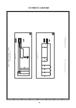
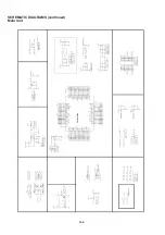
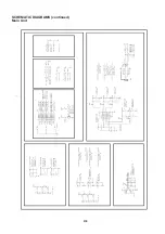
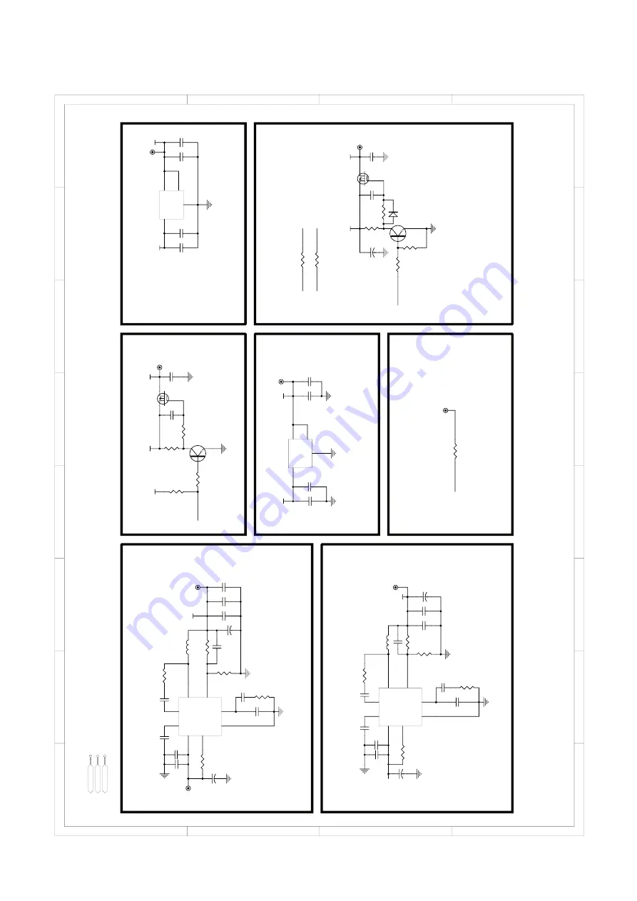
SCHEMATIC DIAGRAMS (continued)
Main Unit

H-3

Summary of Contents for LC-23LE448RU

Page 1: ...et SHARP CORPORATION This document has been published to be used for after sales service only The contents are subject to change without notice Page CONTENTS SERVICING NOTICES ON CHECKING A1 1 HOW TO ORDER PARTS A1 1 IMPORTANT A1 1 ABOUT LEAD FREE SOLDER PbF A1 2 CAUTION WHEN REMOVE THE REAR CABINET A1 2 HOTEL MODE FUNCTION A1 3 GENERAL SPECIFICATIONS A2 1 A2 6 DISASSEMBLY INSTRUCTIONS B1 1 B2 2 H...

Page 2: ... using the 500V insulation resistance meter which is indicated in the circuit diagram or the Note 1 table of parts as a mark the designated 4 If the insulation resistance is less than 1M parts must be used ohm the inspection repair should be required required 4 BE CAREFUL WITH THE LCD PANEL Note 1 If you have not the 500V insulation Avoid a shock to the panel while servicing resistance meter use a...

Page 3: ...ith the printed circuit board with PbF printing must be serviced with lead free solder When soldering or unsoldering completely remove all of the solder from the pins or solder area and be sure to heat the soldering points with the lead free solder until it melts sufficiently Recommendations Recommended lead free solder composition is Sn 3 0Ag 0 5Cu 1 Remove SCREWs from COVER BACK ASS Y and hold t...

Page 4: ...TING menu then press ENTER button 4 Select the Hotel Mode menu 5 Using the LEFT RIGHT button on the remote control please select 6 Then press the ENTER button 7 Please input the password 0000 Then press the ENTER button 8 The setting items has now been returned to initial value To set the Hotel mode please follow the steps below The Hotel mode setting menu will appear Hotel Mode On TV AV Source Lo...

Page 5: ...EPG Timer 1 W at AC 230 V 50 Hz Per Year kWh Year Protector Power Fuse Yes G 4 Regulation Safety Radiation EN55013 EN55020 EN55022 IEC61000 3 2 IEC61000 3 3 X Radiation G 5 Temperature Operation 0o C 40o C Storage 20o C 60o C Space Around Unit 100mm 4inch G 6 Operating Humidity Less than 80 RH G 7 OSD Language English Simplified Chinese Arabic Thai Persian French Vietnam Russian Malay Portuguese S...

Page 6: ...r On Memory Yes Auto Shut Off Yes Just Clock Function No Game Position No DNR Yes 3D Comb Filter Yes 3D Auto Set Up Fast installation Language Yes Country No TV Location No Auto Power Off Yes Auto tuning Yes CH sort No ATS No Auto clock Digital tuner No Plug in start Yes Picture Setting TV Picture Mode Yes Brightness Contrast Color Yes Tint Yes Sharpness Yes DNR Yes Color Temperature Yes Backlight...

Page 7: ...MA REAL Yes CH Label Yes Reset to Default Yes HD Zoom No Picture Scroll Vertical Position No PFC Power Factor circuit No Freeze frame Yes ATV CVBS in Only Plug and Play No Power Management Yes Hearing Impaired No Audio Description No Power On LED No HDMI Mode No Blue Back Yes Scart Spec Scart1 AV in No AV out No S Video in No RGB in No Scart2 AV in No AV out No S Video in No RGB in No Digital Text...

Page 8: ...o SVGA 800x600 Yes 60Hz XGA 1024x768 Yes 60Hz WXGA 1280x768 Yes 60Hz WXGA 1280x720 Yes 60Hz WXGA 1360x768 Yes 60Hz SXGA 1280x1024 Yes 60Hz WXGA 1440x900 Yes 60Hz WSXGA 1680x1050 No Possible to Display FULL HD 1920x1080 Yes 60Hz 720 480i 4 3 Yes 60Hz 720 480i 16 9 Yes 60Hz 720 480p 4 3 Yes 60Hz 720 480p 16 9 Yes 60Hz 720 576i 4 3 Yes 50Hz 720 576i 16 9 Yes 50Hz 720 576p 4 3 Yes 50Hz 720 576p 16 9 Y...

Page 9: ...n Menu Yes Input Select Enter Yes Menu No Vol Vol 1sec Indicator Power Stand by Yes Green Red On Timer No Terminals Rear Video Input 1 RCA x 1 Audio Input 1 RCA x 2 L R S Input 1 No Video Input 2 No Audio Input 2 No S Input 2 No Video Output No Audio Output No Digital Audio Out Coaxial No Euro Scart 21Pin No Component In RCA x 3 Audio Input Component In use Audio Input1 enable HDMI Input 1 Yes Aud...

Page 10: ...p Test Natural Dropping At 1 Corner 3 Edges 5 Surfaces Height cm 48 ES 15 PP 5 Container Stuffing 2400 Sets 40 hi cub container w Pallet No w Wrapping No G 16 Material Cabinet Cabinet Front PS 94HB Piano Cabinet Rear PS 94V0 NON DECABROM Speaker Box Stand PS 94HB Piano PCB Non Halogen No Eyelet Yes G 17 Environment Environmental standard requirement Green procurement of SHARP Pb Free Phase3 PHASE3...

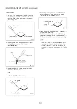
Page 11: ...ield Main A B 1 4 LED MODULE ASS Y Refer to Fig 1 4 1 Unlock the 14 supports 1 2 Remove the LED Module Ass y in the direction of 1 2 COVER BACK ASS Y Refer to Fig 1 2 arrow A B C D Please remove carefully and slowly 1 Remove the 11 screws 1 2 Disconnect the following connectors CD301 CD2201 and CD2202 3 Remove the Cover Back Ass y in the direction of arrow A 4 Remove the 2 screws 2 5 Remove the Sh...

Page 12: ...ng is carried out on all the parts located within 10 mm distance from IC leads Fig 2 1 Masking Tape Cotton Tape IC Blower type IC desoldering machine Tweezers 2 Heat the IC leads using a blower type IC desoldering machine Refer to Fig 2 2 NOTE Do not rotate or move the IC back and forth until IC 4 Peel off the Masking Tape can move back and forth easily after desoldering the leads completely 5 Abs...

Page 13: ...esoldering NOTE 2 Supply the solder from the upper position of IC leads When the IC leads are bent during soldering and or sliding to the lower position of the IC leads repairing do not repair the bending of leads If the Refer to Fig 2 6 bending of leads are repaired the pattern may be damaged So always be sure to replace the IC in this Fig 2 5 Fig 2 8 IC Thin tip Soldering Iron Soldering Iron Sol...

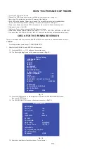
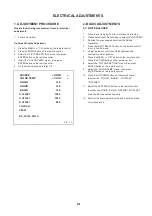
Page 14: ...st easily CAUTION Do not adjust other items except SW INFORMATION 1 Check of the SUM DATA and VERSION on the screen 1 1 Press the MENU 1147 button on the remote control 1 2 The Factory Setting menu on the screen as shown in Fig 1 1 GENERAL SETTING PICTURE SOUND DEBUG ADC ADJUST EMC SETTING Factory Setting SW INFORMATION Software Update USB INIT FAC CHANNEL INIT TV BURN MODE OFF BUILD TIME 2014 07 ...

Page 15: ... button on the remote control 4 Select the COLOR TEMP menu then press 7 Press the DOWN button on the remote control ENTER button on the remote control 8 Select the PICTURE SETTING menu then press 5 On the screen as shown in Fig 1 1 ENTER button on the remote control 9 Select the COLOR TEMP menu then press ENTER button on the remote control SOURCE HDMI 10 Press the UP DOWN button on the remote cont...

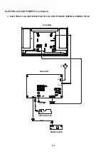
Page 16: ...AC IN CD503 SPEAKER SP301 CP2201 OS2201 REMOCON PCB CD2201 OPERATION PCB CP2202 CN12 CN5 CN6 CN18 CNB1 CNB802 MAIN UNIT 3 ELECTRICAL ADJUSTMENT PARTS LOCATION GUIDE WIRING CONNECTION D 2 ELECTRICAL ADJUSTMENTS continued ...

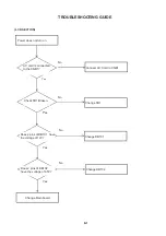
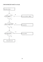
Page 17: ...d to the CNB1 Connect AC Cord to CNB1 No 㪰㪼㫊 Check FB1 Broken Change FB1 No Y Does 2 pins of DB101 have the voltage of 12V Change DB101 Yes No Yes Does 2 pins of DB102 have the voltage of 6 5V Change DB102 No Yes Change Main board E 1 TROUBLESHOOTING GUIDE ...

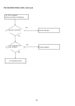
Page 18: ...icture appears but the audio does not appears Is Speaker connected Connect Speaker No Yes Is there signal at pins 1 and 4 of CN18 Change Speaker Yes N No Change Main board E 2 TROUBLESHOOTING GUIDE continued ...

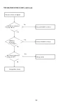
Page 19: ...cted to the CNB802 Connect CP2000 to CNB802 No 㪰㪼㫊 Change Panel Does 1䌾3 pins of CNB802 have the voltage of 11V Yes No Change UB801 Yes No Change Main board Does 1 pins of UB801 have the voltage of 12V E 3 TROUBLESHOOTING GUIDE continued ...

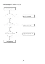
Page 20: ...801 is connected to the CN12 Connect CD2801 to CN12 No Yes Connect CD2801 to Panel Yes No CD2801 is connected to the Panel Change panel Yes No Change Main board CN12 have signal and voltage of 12V E 4 TROUBLESHOOTING GUIDE continued ...

Page 21: ... color Normal Adjust the color setting No Yes Receive the color signal Yes No Is the color signal received Check U9 TSUMV59XE and peripheral circuit Yes No Change Main board Is there color signal at IC U9 E 5 TROUBLESHOOTING GUIDE continued ...

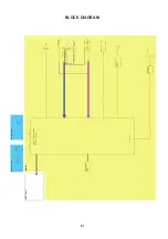
Page 22: ...MV39LE or TSUMV59XE Key A Key B HDMI Connector HDMI Audio Mini Jack PC DVI Audio PC Input D Sub 15 pin PC In Analog RGB HSYNC VSYNC V Audio Component In Jack CVBS In Speaker 䌌 R Pb Pr Y Component Video In Serial FLASH 32Mbit GD25Q16BSIG GIGA SOUND AMP TPA3110LD2PWP R Speaker OUT UBS Silicon Tuner R620D2 F 1 BLOCK DIAGRAM ...

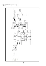
Page 23: ...1 2 VCC OUT CS GND OTP COMP UB101 DB2 DB4 DB1 DB3 PCB102 PCB101 4 EB106 QB101 EB1 EB2 SGND 6 7 11 10 9 8 EB102 EB103 EB101 DB102 DB101 GND 6 5V 12V TB101 LCB1 FB1 CNB1 AC_IN PCB102 PCB101 EB106 SGND GND F 2 BLOCK DIAGRAM continued Power ...

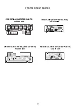
Page 24: ...8 R2210 R2209 C2201 C2202 CP2202 SW2201 SW2202 SW2203 SW2204 SW2205 SW2206 OS2201 D2201 CP2201 OPERATION CHIP MOUNTED PARTS SOLDER SIDE OPERATION INSERTED PARTS SOLDER SIDE REMOCON CHIP MOUNTED PARTS SOLDER SIDE REMOCON INSERTED PARTS SOLDER SIDE G 1 PRINTED CIRCUIT BOARDS ...

Page 25: ...8K 1 16W R2202 2 7K 1 16W R2203 1 8K 1 16W R2204 11K 1 16W G R D2201 LTL 1BEFJ 002A STANDBY POWER 1 2 3 CP2201 A2001WR 5A 1 2 3 4 5 CP2202 A2001WR 3A 1 2 3 Vout B GND OS2201 S R531F H451 B 1 2 3 SW2202 EVQ21505R VOL SW2204 EVQ21505R POWER SW2203 EVQ21505R INPUT ENTER SW2201 EVQ21505R CH SW2205 EVQ21505R VOL SW2206 EVQ21505R CH CD2201 CH252005 CD2202 06EH232202 GND4 KEY B KEY A REMOCON PCB PCBDA0 C...

Page 26: ...M1 N1 N1 N1 VLED VLED VLED LED FB LED LED FB LED FB LED LED CEN948 PCBXX0 LED BAR PCB CD2202 CD2201 CEM846 PCBDA0 REMOCON PCB 12V 12V GND GND NC PWM DIM AT 3 3V LED FB LED VGA R VGA G VGA B NC GND GND GND NC GND NC SDA HS VS SCL GND GND USBP USBN 5V TMDS DATA1 TMDS DATA2 TMDS DATA2 TMDS DATA1 TMDS DATA0 TMDS DATA0 TMDS CLK SH TMDS CLK TMDS CLK TMDS DATA0 SH TMDS DATA1 SH TMDS DATA2 SH HOT PLUG 5V ...

Page 27: ...0402 X7R 10 50V RD4 20Kohm 0402 5 1 16W CD3 0 1uF 0402 Y5V 80 20 16V RD2 12K4ohm 0402 1 1 16W LD2 SCD54TL 4R7M CD20 NC 22pF 0402 NPO 5 50V RD6 10ohm 0402 5 1 16W RD41 10Kohm 0402 5 1 16W CD42 0 1uF 0402 Y5V 80 20 16V RD43 22Kohm 0402 1 1 16W CD41 0 1uF 0402 Y5V 80 20 16V Q4 WPM2341A 3 TR Q8 AO3407A CL2 NC 10uF 0805 Y5V 80 20 10V CL41 NC 10uF 0805 Y5V 80 20 10V CD48 10uF 0805 Y5V 80 20 10V 12V CD17...

Page 28: ...74 LVA2M 53 LVA1P 54 LVA1M 55 LVA0P 56 LVA0M 57 LVB2P 62 LVA2P 52 SDI 73 SCZ 75 RX0P 94 DDCD_DA 95 RX1N 96 SOGIN0 5 AUOUTL0 30 AUOUTR0 31 AUOUTL1 32 AUOUTR1 33 XOUT 34 XIN 35 AVDD_DMPLL 36 VDDC 2 HSYNC0 3 BIN0P 4 RIN0P 8 VSYNC0 9 AVDD_25 10 CVBS1 18 CVBS0 19 VCOM 20 CVBSOUT 21 AUR0 24 AUVAG 25 AUL4 26 AUR4 27 AUL5 28 AUR5 29 AVDD_AU33 22 AVDD_REF 37 VIFP 38 GPIO56 43 GPIO57 44 AVDD_PLL 45 VDD 46 G...

Page 29: ...A K D3 NC AVLC18S02003 A K D5 NC AVLC18S02003 A K D7 NC AVLC18S02003 A K D1 NC AVLC18S02003 A K D2 NC AVLC18S02003 YPbPr1 Y YPbPr1 Pb YPbPr1 Pr R58 33ohm 0402 5 1 16W C56 0 047uF 0402 X7R 1 0 16V YPbPr_Pb_IN C58 1000pF 0402 X7R 1 0 50V R60 33ohm 0402 5 1 16W C59 0 047uF 0402 X7R 1 0 16V YPbPr_SOG YPbPr_Y_IN R61 33ohm 0402 5 1 16W C60 0 047uF 0402 X7R 1 0 16V YPbPr_Pr_IN YPbPr1 Y YPbPr1 Pr YPbPr1 P...

Page 30: ...16V CA13 0 22uF 0402 X5R 10 16V CA22 0 22uF 0402 X5R 10 16V GND AGND AGND AGND CA21 0 22uF 0402 X5R 10 16V CA6 0 22uF 0402 X5R 10 16V AGND CA8 0 22uF 0402 X5R 10 16V CA20 0 22uF 0402 X5R 10 16V CA35 0 1uF 0402 Y5V 80 20 16V CA15 1uF 0402 X5R 20 10V CA4 1uF 0402 X5R 20 10V M_5V RA1 10Kohm 0402 5 1 16W RA01 NC 0ohm 0402 5 1 16W GND AGND RA02 NC 0ohm 0402 5 1 16W GAIN0 GAIN0 GAIN0 RA3 NC 0ohm 0402 5 ...

Page 31: ... tf2p 20 tf2n 19 gnd 25 dvss 11 ifp_n 12 vagc 14 ifp_p 13 avdd 3 UT2 R620D2 CT7 10pF 0402 NPO 5 50V RT2 5R1ohm 0402 5 1 16W RT5 0ohm 0402 5 1 16W TUNER VCC TAGC IF AGC R106 10Kohm 0402 5 1 16W C86 0 047uF 0402 X7R 10 16V R108 100ohm 0402 5 1 16W IF AGC C127 0 1uF 0402 Y5V 80 20 16V R194 10Kohm 0402 5 1 16W IF AGC TUNER_SCL TUNER_SDA R193 100ohm 0402 5 1 16W R195 100ohm 0402 5 1 16W C128 30pF 0402 ...

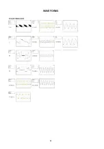
Page 32: ...㪰 I 1 WAVEFORMS ...
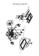
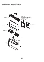
Page 33: ... 111 101A 101C 101 101B 101D 101D 101E 101E 109 203 203 203 203 207 108 MAIN001 MAIN UNIT 106 104 PCBXX0 LED BAR ASS Y 113 113 103A 103 103B 103B 103B 103B 105 102A 102B 102C 102D 102F 102E 102G 102G 102G 102G 102G 102H 102 201 201 201 201 202 205 205 205 205 206 206 206 206 J1 1 MECHANICAL EXPLODED VIEW ...

Page 34: ...FILM BAG 9JD791WHAA549 FILM BAG 9JD791WHAA558 PACKAGE BOTTOM PACKAGE BOTTOM PACKAGE TOP TM101 SCREW ASS Y POLYBAG INSTRUCTION RED CAUTION GUARANTEE CARD INSTRUCTION BOOK RU KZ EAC SAFETY SHEET J1 2 MECHANICAL EXPLODED VIEW continued ...

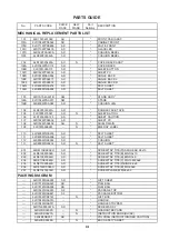
Page 35: ...WPA0002 AD SHEET PC 108 9JD752WSA0836 AG N SHIELD MAIN 109 9JD7230008691 N ENERGY LABEL 110 9JD800WQ0A230 AD FELT SHEET 111 9JD800WQ0A268 AD FELT SHEET 112 9JD800WRA0032 AD CUSHION 113 9JD800WQ00233 AD N FELT SHEET 201 9JD8110K26A0U AD SCREW TAP TITE P LAMI HEAD 2 6x10 202 9JD8109230A0S AD SCREW TAP TITE B BIND 3x10 203 9JD810923060U AD SCREW TAP TITE B BIND 3x6 204 9JD8110E2680U AD SCREW TAP TITE...

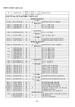
Page 36: ... SWITCH TACT EVQ21505R SW2202 9JD0504101T34 AC SWITCH TACT EVQ21505R SW2203 9JD0504101T34 AC SWITCH TACT EVQ21505R SW2204 9JD0504101T34 AC SWITCH TACT EVQ21505R SW2205 9JD0504101T34 AC SWITCH TACT EVQ21505R SW2206 9JD0504101T34 AC SWITCH TACT EVQ21505R CP2202 9JD06GG230019 AD CONNECTOR PCB SIDE A2001WR 3A CD503 9JD120H6HD003 AL N CORD AC BUSH A2A7B20061216700 R2 BT001 9JD141U004021 AD BATTERY MANG...

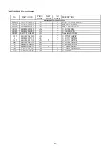
Page 37: ... OB3350CPA QB801 9JDTKFTOD4420 AH Transistor AOD442 UD11 9JDIM2F0275G0 AG IC RT7257GHZSP U1 9JDIM2F911170 AF IC LC1117CLTR33 UL41 9JDIM2F9117C0 AD N IC LC1117CLTR18 UD1 9JDIM2F0237C0 AE IC RT7237CHGSP U8 9JDIN7J032BS0 AH IC GD25Q32BSIG U9 9JDIN7J059XE1 BC N IC TSUMV59XE V1 UA1 9JDIN7J031100 AM IC TPA3110D2PWPR UT2 9JDIN7J0620D0 AM IC R620D2 No PARTS CODE DESCRIPTION MAIN PARTS IN MAIN UNIT K 3 PAR...

Page 38: ... RIGHTS RESERVED No part of this publication may be reproduced stored in a retrieval system or transmitted in any form or by any means electronic mechanical photocopying recording or otherwise without prior written permission of the publisher SHARP CORPORATION ...

Reviews: