


10
LC-24LE240
Operation Manual (Continued)
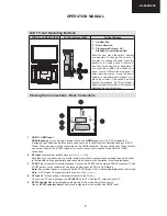
Using USB Inputs
USB Connection
You can connect a USB hard disk drive or USB
•
memory stick to your TV by using the USB inputs
of the TV. This feature allows you to play
fi
les stored
in a USB drive or record programmes.
2.5” and 3.5” inch (hdd with external power supply)
•
external hard disk drives are supported.
To record a programme, you should
fi
rst connect
•
a USB disk to your TV while the TV is switched
off. You should then switch on the TV to enable
recording feature. Otherwise, recording feature will
not be available.
If one or more partitions of your hard drive are exFAT
•
formatted, none or less partitions might be visible,
even if they are formatted with a different
fi
le system
than exFat.
IMPORTANT !
You may back up your
fi
les before making any
•
connections to the TV set in order to avoid any
possible data loss. Note that manufacturer will not
be responsible for any
fi
le damage or dataloss.
It is possible that certain types of USB devices (e.g.
•
MP3 Players) or USB hard disk drives/memory sticks
may not be compatible with this TV.
IMPORTANT:
The TV supports only FAT32 and
NTFS disk formatting. However, NTFS format is not
supported for recording features. For recording, if you
connect a USB disk with NTFS format, the TV will ask
you to format the content. See the section, “Format
Disk” in the following pages for more information on
disk formatting.
Note that ALL the data stored on the USB disk will
be lost and then the disk format will be converted to
FAT32 in such a case.
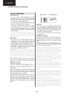
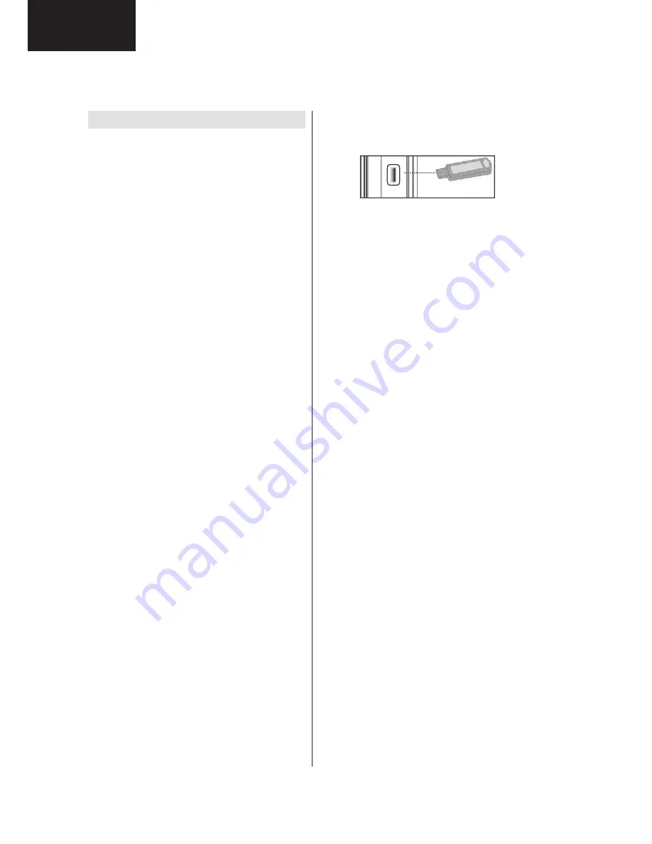
USB Disk Connection
• Plug your USB device to the USB input of the TV.
Note: Plug or unplug your USB disk while the TV is
switched off.
Note: If you are going to connect a USB hard disk drive
to the TV set, USB connection cable used between
the disk drive and the TV should have a USB logo
and should be as short as possible.
Note: While formatting a USB hard disk that has 1TB
(Tera Byte) or more
fi
le capacity, you can experience
problems with the formatting process. In such a
case, you should format the disk with your personal
computer and the formatted disk type should be
FAT32.
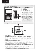
SIDE VIEW USB MEMORY
5Vdc
Max:500mA
USB
CAUTION !
Quickly plugging and unplugging USB devices,
•
is a very hazardous operation. Especially, do not
repeatedly quickly plug and unplug the drive. This
may cause physical damage to the USB player and
especially the USB device itself.
Do not pull out USB module while playing or
•
recording a
fi
le.
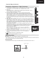
Programme Recording
To record a programme, you should
fi
rst connect a
USB disk to your TV while the TV is switched off.
You should then switch on the TV to enable recording
feature.
IMPORTANT: When using a new USB hard disk drive,
it is recommended that you
fi
rst format the disk using
your TV’s “Format Disk” option.
For using recording function, you should connect a
•
USB disk or an external hard disk drive to the TV
and connected USB disk should have at least 1 GB
capacity and should have 2.0 speed compatibility.
If the connected USB device does not support 2.0
speed, an error message will be displayed.
Note: Recorded programmes are saved into the
connected USB disk. If desired, you can store/copy
recordings on a computer; however, these
fi
les will
not be available to be played on a computer. You can
play the recordings only via your TV.
For more information on recording programmes,
•
see sections “Instant Recording”, “Timeshifting”,
“Electronic Programme Guide”, “Recordings Library”
or “Recording Timers” in the following parts.
Recorded programmes are split into 4GB
Recorded programmes are split into 4GB
••
partitions.
partitions.
Recorded programmes are stored in the following
•
directory of the connected USB disk: \DVR\RECS.
All recordings are indicated with a number. A text
(txt)
fi
le is created for each recording. This text
file includes information such as broadcaster,
programme, and recording time.
Timeshifting may be stopped according to USB
•
device write speed. If the USB device speed is not
enough for video stream bitrate, timeshifting may
be stopped and recording may fail. If HD service
bitrate is greater than 13 Mbp/sec. some freeze can
be seen during timeshifting on both USB disk and
on external HDD.
A01_MB62_[GB]_1910UK_IDTV_TC_PVR_BRONZE19_24942LED_ROCKER_ZIGGO_10077476_50211339.indd 11
15.03.2012 16:27:17
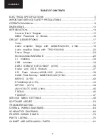
Summary of Contents for LC-24LE240E Operation
Page 6: ...6 LC 24LE240 End of life disposal ...
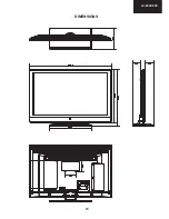
Page 13: ...13 LC 24LE240 DIMENSIONS ...
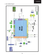
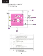
Page 15: ...15 LC 24LE240 1 General Block Diagram ...
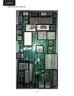
Page 16: ...16 LC 24LE240 2 MB62 Placement of Blocks TU3 ...
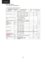
Page 20: ...20 LC 24LE240 2 3 Absolute ratings 2 3 1 Electrical characteristics ...
Page 21: ...21 LC 24LE240 3TIVEXMRK 7TIGMJMGEXMSRW 4MRRMRK 2 3 2 Operating Specifications 2 3 Pining ...
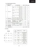
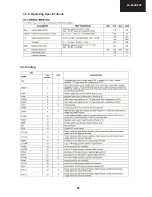
Page 23: ...23 LC 24LE240 3TIVEXMRK 7TIGMJMGEXMSRW 3 3 2 Operating Specifications 3 4 Pinning ...
Page 28: ...28 LC 24LE240 1 4S IV 1EREKIQIRX MXL 47 47 47 4 1 4S IV 1EREKIQIRX MXL 4 4 4 ...
Page 36: ...36 LC 24LE240 4MRRMRK 8 3 Pinning ...
Page 48: ...48 LC 24LE240 18 2 HDMI CN707 CN708 18 3 VGA CN711 ...
Page 50: ...50 LC 24LE240 1 2 Audio Settings 1 3 Options Options 1 ...
Page 51: ...51 LC 24LE240 Options 2 1 4 Tuning Settings ...
Page 62: ...62 LC 24LE240 Notes ...
Page 72: ...72 LC 24LE240 POWER SUPPLY Diagram 1 2 3 4 5 6 7 8 9 10 11 12 13 14 15 16 I H G F E D C B A ...
Page 73: ...73 LC 24LE240 1 2 3 4 5 6 7 8 9 10 11 12 13 14 15 16 I H G F E D C B A Led Converter Diagram ...
Page 83: ...83 LC 24LE240 NOTES ...