background image

PRICE

RANK

DESCRIPTION

NO.

PART CODE

NO.

PARTS CODE

PRICE

RANK

DESCRIPTION

MD-MS702/MD-MS701W

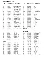
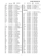
R767,768

VRS-CY1JB102J

J

AA

1 kohm,1/16W

R801

VRS-CY1JB684D

J

AA

680 kohms,1/16W

R802

VRS-CY1JB394D

J

AA

390 kohms,1/16W

R803,804

VRS-CY1JB104J

J

AA

100 kohm,1/16W

R805

VRS-CY1JB474D

J

AA

470 kohms,1/16W

R806

VRS-CY1JB684D

J

AA

680 kohms,1/16W

R807

VRS-CY1JB273D

J

AA

27 kohms,1/16W

R808

VRS-CY1JB393D

J

AA

39 kohms,1/16W

R809

VRS-CY1JB104J

J

AA

100 kohm,1/16W

R810,811

VRS-CY1JB184D

J

AA

180 kohms,1/16W

R814,815

VRS-CY1JB392D

J

AA

3.9 kohms,1/16W

R816

VRS-CY1JB122D

J

AA

1.2 kohms,1/16W

R817

VRS-TV2AB223J

J

AA

22 kohms,1/10W

R818

VRS-CY1JB103J

J

AA

10 kohm,1/16W

R819

VRS-CY1JB271J

J

AA

270 ohms,1/16W

R821

VRS-CY1JB104J

J

AA

100 kohm,1/16W

R823

VRS-CY1JB104J

J

AA

100 kohm,1/16W

R824

VRS-CY1JB153J

J

AA

15 kohms,1/16W

R826

VRS-CY1JB103J

J

AA

10 kohm,1/16W

R827

VRS-CY1JB304D

J

AA

300 kohms,1/16W

R828

VRS-CY1JB274D

J

AA

270 kohms,1/16W

R829

VRS-CY1JB333J

J

AA

33 kohms,1/16W

R831

VRS-CY1JB104J

J

AA

100 kohm,1/16W

R832

VRS-CY1JB335J

J

AA

3.3 Mohms,1/16W

R841

VRS-CY1JB104J

J

AA

100 kohm,1/16W

R843

VRS-CY1JB104J

J

AA

100 kohm,1/16W

R844

VRS-CY1JB153J

J

AA

15 kohms,1/16W

R846

VRS-CY1JB103J

J

AA

10 kohm,1/16W

R847

VRS-CY1JB334D

J

AA

330 kohms,1/16W

R848

VRS-CY1JB224D

J

AA

220 kohms,1/16W

R849

VRS-CY1JB333J

J

AA

33 kohms,1/16W

R851

VRS-CY1JB104J

J

AA

100 kohm,1/16W

R852

VRS-CY1JB155J

J

AA

1.5 Mohms,1/16W

R861

VRS-CY1JB104J

J

AA

100 kohm,1/16W

R872

VRS-CY1JB104J

J

AA

100 kohm,1/16W

R873

VRS-CY1JB102J

J

AA

1 kohm,1/16W

R874

VRS-CY1JB474J

J

AA

470 kohms,1/16W

R875~882

VRS-CY1JB104J

J

AA

100 kohm,1/16W

R901,902

VRS-CY1JB1R0J

J

AA

1 ohm,1/16W

R903

VRS-CY1JB151J

J

AA

150 ohms,1/16W

R904

VRS-CY1JB223J

J

AA

22 kohms,1/16W

R905

VRS-CY1JB104J

J

AA

100 kohm,1/16W

R906

VRS-CY1JB274J

J

AA

270 kohms,1/16W

R907

VRS-CY1JB184J

J

AA

180 kohms,1/16W

R908

VRS-CY1JB104J

J

AA

100 kohm,1/16W

R909

VRS-CY1JB103J

J

AA

10 kohm,1/16W

R921

VRS-CY1JB331J

J

AA

330 ohms,1/16W

R922

VRS-CY1JB104J

J

AA

100 kohm,1/16W

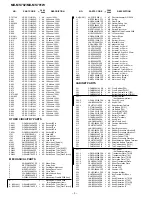
OTHER CIRCUITRY PARTS

CN101

QCNCW801XAFZZ J

AH

Socket,22Pin

CN451

QCNCW749PAFZZ J

AE

Socket,14Pin

CN482

QCNCW804GAFZZ J

AD

Socket,7Pin

CN601

QCNCW804RAFZZ J

AE

Socket,16Pin

CN701

QCNCWWQ33AFZZ J

AE

Socket,33Pin

J701

VHPGP1FB65R-1

J

AP

Jack,LINE

J702

QJAKM0189AFZZ

J

AE

Jack,MIC IN

J703

QJAKM0201AFZZ

J

AH

Jack,Headphones

J801

QJAKC0136AFZZ

J

AD

Jack,DC IN

M901

RMOTV0500AFZZ

J

AT

Motor Ass’y [Spindle]

M902

RMOTV0503AFZZ

J

AF

Motor Ass’y [Sled]

M903

RMOTV0501AFM1

J

AS

Motor Ass’y [Lift]

SW401

QSW-M0001AWZZ J

AD

Switch,Push Type [EJECT]

SW402

QSW-S0948AFZZ

J

AC

Switch,Slide Type [HOLD]

SW901

QSW-M0169AFZZ

J

AD

Switch,Push Type [Disc In]

SW902

QSW-M0170AFZZ

J

AD

Switch,Push Type [Disc Protect]

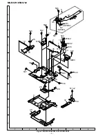
MECHANICAL PARTS

1

NGERH0597AFZZ

J

AC

Wheel,Drive

2

NSFTD0328AFZZ

J

AE

Screw,Drive

3

LHLDX3136AFM1

J

AH

Cartridge Holder Ass’y

4

MSPRT1607AFFJ

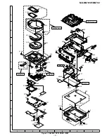
J

AB

Spring,Cancel Lever

5

MLEVF2598AFFW

J

AD

Lever,Eject

6

LCHSM0931AFM1

J

AN

Main Chassis Ass’y

7

PCUSG0599AFZZ

J

AB

Cushion

8

QPWBH0306AFM1 J

AQ Mechanism Flexible PWB Ass’y

8- 1

————

J

Mechanism Flexible PWB

(Not Replacement Item)

8- 2(SW901)

QSW-M0169AFZZ

J

AD

Switch,Push Type [Disc In]

8- 3(SW902)

QSW-M0170AFZZ

J

AD

Switch,Push Type [Disc Protect]

8- 4(PH901)

VHPGP1S93K/-1

J

AF

Photo Interrupter,GP1S93K

11

MSPRP0881AFFJ

J

AB

Spring,

13

NGERH0596AFZZ

J

AD

Gear,Drive

15

RCTRH8175AFZZ

J

BM Optical Pickup Unit

16

MSPRP0880AFFJ

J

AC

Spring,Drive Grip

18

NSFTM0292AFFW

J

AC

Shaft,Guide

20

MSPRT1604AFFJ

J

AB

Spring,Eject Lever

23

QPWBH0307AFZZ

J

AF

Magnetic Head Flexible PWB

25

MLEVF2599AFM1

J

AE

Lift Lever Ass’y

26

NGERH0595AFZZ

J

AC

Gear,Lift Drive

28

MLEVF2600AFFW

J

AD

Lever,Lift

29

MSPRD1353AFFJ

J

AB

Spring,Lift Lever

30

LANGF1588AFFW

J

AD

Bracket,Pickup

32

RCILH0109AFZZ

J

AN

Magnetic Head

501

XSPSN14P01800

J

AA

Screw,ø1.4

×

1.8mm

502

LX-JZ0154AFZZ

J

AA

Screw,ø1.4

×

2.8mm

503

LX-BZ0823AFZZ

J

AA

Screw,ø1.4

×

1.2mm

504

LX-WZ9290AFZZ

J

AA

Washer,ø0.8

×

ø2.4

×

0.25mm

505

LX-BZ0800AFZZ

J

AA

Screw,ø1.4

×

2.5mm

506

LX-JZ0146AFZZ

J

AA

Screw,ø1.7

×

2.5mm

507

LX-BZ0804AFFF

J

AA

Screw,ø1.4

×

2.2mm

508

LX-BZ0960AFZZ

J

AB

Screw,ø1.4

×

1.5mm

509

XSPSN14P01200

J

AA

Screw,ø1.4

×

1.2mm

510

LX-WZ9164AFZZ

J

AA

Washer,ø1

×

ø2.4

×

0.25mm

511

LX-BZ0959AFZZ

J

AB

Screw,ø1.4

×

1.8mm

512

LX-WZ9293AFZZ

J

AA

Washer,ø2.7

×

ø5

×

0.25mm

513

LX-WZ9294AFZZ

J

AA

Washer,ø1

×

ø2.4

×

0.15mm

514

XTPSF14P01800

J

Screw,ø1.4

×

1.8mm

M901

RMOTV0500AFZZ

J

AT

Motor Ass’y [Spindle]

M902

RMOTV0503AFZZ

J

AF

Motor Ass’y [Sled]

M903

RMOTV0501AFM1

J

AS

Motor Ass’y [Lift]

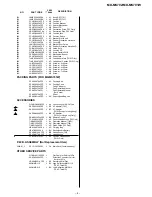
CABINET PARTS

201

GCABB2841AFSB

J

AG Front Cabinet [702]

201

GCABB2841AFSC

J

AG Front Cabinet [701W]

202

CCABD4355AF01

J

AX

Bottom Cabinet Ass’y [702]

202

CCABD4357AF01

J

Bottom Cabinet Ass’y [701W]

202- 1

   ————

Bottom Cabinet

(Not Replacement Item)

202- 2

GCOVA2218AFSA

J

AB

Cover,DC Jack

202- 3

JKNBZ2040AFSA

J

AD

Knob,HOLD

202- 4

PSHET0371AFZZ

J

AC

Sheet,Bottom Cabinet

203

GFTAB1348AFSA

J

AC

Lid,Battery [701W]

203

GFTAB1348AFSB

J

AC

Lid,Battery [702]

205

GCOVA2217AFSA

J

AD

Cover,Eject [701W]

205

GCOVA2217AFSB

J

AD

Cover,EJECT [702]

206

QTANZ9150AFFQ

J

AC

Battery Terminal,-

207

QTANZ9149AFFQ

J

AC

Battery Te

208

JKNBK0526AFSA

J

AE

Knob,Eject

209

LANGK0934AFM1

J

AN

Main Frame Ass’y

210

PCUSG0649AFZZ

J

AB

Cushion Machanism

211

PSHET0373AFZZ

J

AC

Sheet

213

LANGZ0334AFM1

J

AN

Eject Bracket Ass’y

214

PCUSG0635AFZZ

J

AA

Rubber,Preventive Vibration B

215

PCUSG0636AFZZ

J

AA

Rubber,Preventive Vibration C

216

GCABA2839AFSA

J

AF

Center Cabinet [701W]

216

GCABA2839AFSB

J

AF

Center Cabinet [702]

217

PCUSG0534AFZZ

J

AC

Rubber,Preventive Vibration

219

PSHET0378AFZZ

J

AB

Sheet,Extention Battery Terminal

220

QTANZ9151AFFQ

J

AG Extention Battery Terminal

221

CCABC4329AF01

J

AY

Top Cabinet Ass’y [701W]

221

CCABC4330AF01

J

AZ

Top Cabinet Ass’y [702]

221- 1

   ————

Top Cabinet

(Not Replacement Item)

221- 2

HDECQ0528AFSA

J

AG Transparent Plate [701W]

221- 2

HDECQ0533AFSA

J

AG Transparent Plate [702]

221- 3

HDECQ0529AFSA

J

AM Decoration Plate [701W]

221- 3

HDECQ0529AFSB

J

AM Decoration Plate [702]

221- 4

PSHEZ0817AFZZ

J

AC

Sheet,Transparent Plate

221- 5

PSHEZ0818AFZZ

J

AC

Sheet,Decoration Plate

226

LANGK0935AFFW

J

AH

Bracket,Knob

227

LHLDZ1706AFZZ

J

AD

Holder,LCD

228

PCUSG0648AFZZ

J

AB

Cushion,LCD

229

PCUSG0651AFZZ

J

AB

Cushion,Bracket

231

RUNTK0442AFZZ

J

AP

Key Flexible PWB Ass’y

232

RUNTZ0655AFZZ

J

AZ

LCD

233

JKNBZ2042AFSA

J

AK

Knob,Operation A [701W]

233

JKNBZ2042AFSB

J

AF

Knob,Oparetion A [702]

234

JKNBZ2043AFSA

J

AE

Knob,Operation D [701W]

234

JKNBZ2047AFSA

J

AG Knob,Operation D [702]

235

JKNBZ2044AFSA

J

AC

Knob,Operation B

– 3 –

Summary of Contents for MD-MS702

Page 1: ...TIC DIAGRAM WIRING SIDE OF P W BOARD 32 WAVEFORMS OF CD CIRCUIT 43 TROUBLE SHOOTING 44 FUNCTION TABLE OF IC 47 PARTS GUIDE EXPLODED VIEW PACKING OF THE SET MD MS702 ONLY In the interests of user safety the set should be restored to its original condition and only parts identical to those specified should be used MD MS701W MD MS702 SERVICE MANUAL SHARP CORPORATION No S1806MDMS701W This document has...

Page 2: ...DAREN UTSÄTTAS FÖR OSYNLIG LASERSTRÅLNING SOM ÖVERSKRIDER GRÄNSEN FÖR LASERKLASS 1 CAUTION INVISIBLE LASER RADIATION WHEN OPEN AND INTERLOCKS DEFEATED AVOID EXPOSURE TO BEAM VARNING OSYNLIG LASERSTRÅLNING NÄR DENNA DEL ÄR ÖPPNAD OCH SPÄRRAR ÄR URKOPPLADE STRÅLEN ÄR FARLIG ADVARSEL USYNLIG LASERSTRÅLING NÅR DEKSEL ÅPNES OG SIKKERHEDSLÅS BRYTES UNNGÅ EKSPONERING FOR STRÅLEN VARO AVATTAESSA JA SUOJAL...

Page 3: ...inuous play Approx 5 hours Continuous play Approx 8 hours Continuous play Approx 13 hours FOR A COMPLETE DESCRIPTION OF THE OPERATION OF THIS UNIT PLEASE REFER TO THE OPERATION MANUAL Dimensions Width 87 0 mm 3 7 16 Height 29 4 mm 1 3 16 Depth 81 5 mm 3 7 32 Weight MD MS701W 216 g 0 48 lbs with rechargeable battery MD MS702 219 g 0 49 lbs with rechargeable battery Input socket Line optical digital...

Page 4: ...o Recording Indicator 11 Disc Mode Indicator 12 Disc Name Indicator 13 Track Name Indicator 14 Remaining Recording Time Indicator 15 Total Track Number Display 16 Record Track Mark Button 17 Volume Name Select Buttons 18 Display Lowercase Characters Button 19 Character Button 20 Stop Power Off Charge Button OFF 21 Play Pause Button 22 Fast Reverse Fast Forward Recording Level Control Cursor Button...

Page 5: ...re performed some sounds may be skipped whilst cueing and reviewing A track number can be created in the middle of a track If there are scratches or dust on a MiniDisc the track numbers following that track will be increased by one MiniDiscs are recorded using a different system than is used for cassette tapes or DAT recordings Therefore the following conditions may be encountered depending on how...

Page 6: ...from a cool place to a warm place When the unit has condensation inside the disc signals cannot be read and the unit may not function properly If this happens remove the disc The condensation should evaporate in approximately 1 hour The unit will then function properly TROUBLESHOOTING If trouble occurs When this product is subjected to strong external interference mechanical shock excessive static...

Page 7: ...sc has not been loaded Load a disc PB DISC PROTECTED The disc is write protected You tried to record on a playback only disc Move the write protection knob back to its original position Replace it with a recordable disc POWER Improper power is being supplied Use one of the specified power sources SORRY Since a track number is currently being located or written to the unit cannot accept your comman...

Page 8: ...e los pasos 1 4 de la sección Grabación sincronizada 2 Press the button Pulse el botón To stop recording Press the OFF button If the unit is left alone after the recording has stopped the power will be turned off approximately 2 minutes later After recording Press the OFF button while in the stop mode To remove the MiniDisc Turn off the power and move the EJECT lever in the direc tion indicated by...

Page 9: ... stop mode If the unit is not operated for at least 2 minutes while in the stop mode the power will be turned off automatically To remove the MiniDisc Turn off the power and move the EJECT lever in the direction indicated by the arrow Para interrumpir la reproducción Pulse el botón durante la reproducción Para reanudar la reproducción pulse de nuevo el botón Para detener la reproducción Pulse el b...

Page 10: ...ed to the MD mecha nism the screw of the part to be fitted to the MD mechanism chassis it may contact the optical pickup resulting in malfunction 4 Whenrepairing paydueattentiontoelectrostaticcharges of IC REMOVAL PROCEDURE STEP FIGURE Bottom Cabinet Top Cabinet Center Cabinet Pull A1 x1 Ø1 4x2mm A1 x1 Ø1 4x2mm A1 x2 Ø1 4x2mm A1 x2 Ø1 4x2mm B1 x1 Ø1 4x2mm B1 x1 Ø1 4x2mm B1 x2 Ø1 4x2mm Figu re 10 1...

Page 11: ...the screw D1 x 2 pc 2 Remove the screw D2 x1 which connects the magnetic head to the head relay flex PWB and remove the soldering joint D3 x2 pcs Note Mount carefully so as not to damage the magnetic head D1 x2 Ø1 4x1 8mm D1 x1 Ø1 4x1 5mm Pickup Unit Magnetic Head Solder joint D3 x2 Figure 11 4 How to remove the lift motor See Fig 11 2 1 Remove the solder joint B1 x 2 of slide motor lead wire 2 Re...

Page 12: ...n jump test Continuous playback is performed error rate display jump test 5 RESULT 1 Mode The value adjusted in AUTO1 or MANUAL1 is indicated Execution in servo OFF state 6 RESULT 2 Mode The value adjusted in AUTO 2 or MANUAL 2 is indicated Adjustment value is changed manually error rate display jump test 7 TEST PLAY Mode Continuous playback from the specified address is performed 1 line 10 lines ...

Page 13: ...isplayed If the VOL UP button is pressed during setting indication the setting increases If the VOL DOWN button is pressed the setting reduces And then the new setting is stored in the RAM When the VOL UP DOWN button is held down the setting changes continuously one cycle being 100 ms If the STOP button is pressed during RESULT1 menu or measurement value indication or set value indication the stat...

Page 14: ...ection Selection of sound volume BASS etc is possible without indication Recording is also possible 11 Error data display Mode Reversing when SKIP DOWN button is pressed When the STOP button is pressed while the error data indication menu appears or during error data indication the mode changes to the TEST mode stop state Error data 0 is the latest error Error which occurred in the TEST mode is al...

Page 15: ...e Setting Method 11 Set according to the E2 PROM DATA LIST 12 Press the Stop button T E S T 13 Press the Stop button 14 After data is written in E2 PROM turn off power 15 Restore protection of E2 PROM Disconnect connection made in Step 2 above E2 PROM IC402 writing procedure 1 Procedure to replace E2 PROM and write initial value of microcomputer in E2 PROM 2 Temperature reference setting method 1 ...

Page 16: ... C Determining the temperature correction value Temperature detection characteristics formula Ambient temperature o C 2 876 x TEMP input AD value 463 Hence TEMP input AD value 463 Ambient temperature 2 876 The reference temperature 23 6o C is taken as a reference it is taken as 0 Whenever the input AD value changes by 1 temperature is determined For temperature correction the input AD value is inv...

Page 17: ...6 H I N 1 _ D 4 H I N 2 _ 6 7 H C T R _ 6 D H C T 2 _ 1 4 H C T 3 _ 0 3 H C T 4 _ 6 4 H C T 5 _ 7 4 H C T 6 _ 0 8 H C T 7 _ 0 0 H S P M _ 0 0 H M S L _ 8 0 H R S L _ 0 0 H BASS setting Item display Set values B S 1 _ 0 2 H B S 2 _ A 4 H B S 3 _ C 4 H Item display Set values F G _ _ 6 3 H F F 1 _ 7 0 H F F 2 _ F 0 H F Z H _ E D H F L n _ 0 9 H D J G _ 1 4 H F R V _ 0 0 H F P f _ 8 8 H F L V _ 1 9 H...

Page 18: ...DOWN SKIP DOWN SKIP UP When the STOP button is pressed in specific menu the TEST MODE STOP state is set Preautomatic Adjustment menu Preadjustment error adjustment value output During preadjustment adjustment Adjustment error Normal end Preadjustment normal end adjustment value output During ATT automatic adjustment PLAY PLAY A U T O 1 Preautomatic Adjustment A D J O K A D J N G A T 2 A T 1 When t...

Page 19: ...entative measurement Measurement value E signal offset EINO tentative measurement Measurement value F signal offset FINO tentative measurement Measurement value Laser On Play Power RF side focus gain coarse adjustment Gain setting A ATT focus tentative setting ATT setting B ATT focus tentative setting ATT setting RF side pit section tracking gain adjustment Gain setting Pit section adjustment COUT...

Page 20: ...n laser ON state without disc the laser power is changed as follows when the BASS key is pressed L O N M Play power Max power BASS BASS BASS Record power RF side focus gain coarse adjustment A ATT focus tentative setting B ATT focus tentative setting ABMXO measurement value display REPEAT mark lighting R F g S a S b A B DISP DISP In the setting display sate the value of selected digit changes in t...

Page 21: ...is started when the P MODE key is pressed in continuous playback state In laser ON state without disc the laser power is changed as follows if the BASS key is pressed record playback machine only L O N M Play power Max power BASS BASS BASS Record power P MODE P MODE P MODE In the specific setting display state the setting change digit changes when the P MODE key is pressed 1st digit initial value ...

Page 22: ...tting S gain High B signal offset measurement value setting S gain High E signal offset measurement value setting S gain High F signal offset measurement value setting S gain Low A signal offset measurement value setting S gain Low B signal offset measurement value setting S gain Low E signal offset measurement value setting S gain Low F signal offset measurement value setting TCRS signal offset m...

Page 23: ...ck groove section Address High reflection pit section B ATT focus setting High reflection groovesection B ATT focus setting ATT setting P MODE S Q A P H B L B When the STOP button is pressed in specific menu the TEST MODE STOP state is set In the start address set state the start address changes as follows when the DISP key is pressed 0 0 5 0 H initial value 0 3 C 0 H 0 7 0 0 H 0 8 A 0 H A d 0 0 5...

Page 24: ... DOWN key is pressed In the continuous record state and start address set state the record laser power changes in t he range of 0h to Fh when the VOL UP DOWN key is pressed A d 0 0 5 0 1st digit initial value 2nd digit 3rd digit A d 0 0 5 0 BASS A d 0 0 5 0 BASS BASS INNER switch position measurement menu Continuous playback pit section Address PLAY I N N E R Inner Switch Position Measurement S Q ...

Page 25: ...WN E 5 SKIP UP SKIP DOWN E 6 SKIP UP SKIP DOWN E 7 SKIP UP SKIP DOWN E 8 SKIP UP SKIP DOWN E 9 SKIP UP SKIP DOWN Error history clear Error history display When the STOP button is pressed in specific menu the TEST MODE STOP state is set EEPROM setting menu Focus setting menu Spin setting menu Tracking setting menu Sled setting menu BASS setting menu TEMP setting menu Adjustment setting menu Digital...

Page 26: ...WN Spin setting menu Spin system loop filter gain constant setting until servo is turned on setting Spin system loop filter again constant setting after servo is turned on internal periphery setting Spin system loop filter gain constant setting after servo is turned on center setting Spin system loop filter gain constant setting after servo is turned on externalperiphery setting Spin system loop f...

Page 27: ... when the VOL UP DOWN key is pressed The upper limit varies depending on the items S C o SKIP UP SKIP DOWN S C t SKIP UP SKIP DOWN S C m SKIP UP SKIP DOWN D B O SKIP UP SKIP DOWN C L p SKIP UP SKIP DOWN C L r SKIP UP SKIP DOWN W T m SKIP UP SKIP DOWN Slide setting menu Slide system loop filter gain constant setting setting Slide system filter specific constant 2 setting setting Slide drive PWM dut...

Page 28: ...eflection pit section Digital EQ tap factor B C setting High reflection pit section Autolevel slicer gain setting High reflection pit section Autolevel slicer slice level offset setting Lows reflection pit section Digital EQ tap factor A D setting Low reflection groove section digital EQ tap factor A D setting Lows reflection pit section Digital EQ tap factor B C setting Low reflection pit section...

Page 29: ... machine C T 0 C T 1 SKIP UP SKIP DOWN P W L SKIP UP SKIP DOWN R C 0 SKIP UP SKIP DOWN R C 1 SKIP UP SKIP DOWN S Y C SKIP UP SKIP DOWN D R 1 SKIP UP SKIP DOWN D R 2 SKIP UP SKIP DOWN I N 1 SKIP UP SKIP DOWN I N 2 SKIP UP SKIP DOWN I N R SKIP UP SKIP DOWN C T 2 SKIP UP SKIP DOWN C T 3 SKIP UP SKIP DOWN C T 4 SKIP UP SKIP DOWN C T 5 SKIP UP SKIP DOWN C T 6 SKIP UP SKIP DOWN Continued to the next pag...

Page 30: ...itor without such a symbol is microfarad As to electro lytic capacitor the expression capacitance withstand volt age is used CH TH RH UJ Temperature compensation ML Mylar type The indicated voltage in each section is the one measured by Digital Multimeter between such a section and the chas sis with no signal given Parts marked with are important for maintaining the safety of the set Be sure to re...

Page 31: ...C VEE IR3R54N AUDIO AMP VCC VEE 6 8 DC IN RIPPLE FILTER DIGITAL INPUT OPTICAL INPUT UNIT LINE INPUT LINE OUT MIC IN HEAD PHONES 4 5V REGULATOR ON OFF REMOTE CONTROL POWER SELECT N ch MOS FET 3V DC DCONVERTER BATTERY VOLTAGE REGULATOR CONSTANT CURRENT DRIVE RECHARGEABLE BATTERY OPIC POWER SELECT CHARGE DRIVER VCC 2 8 2 5 F IC901 2 5 LB1638 IC651 2 5 2 2 2 5 2 5 2 5 2 5 2 5 74ACT02 IC351 IC101 IC601...

Page 32: ...CNT1 RAA10 ACRCER PLCK SYRS FEMON DADATA ADDATA DFCK BCLK LRCK DGND VDD3 DOUT DIN X1O X1I VPD VXI ADPON DAPON OPTCNT DCNT1 EMPH1 LDCNT2 X700KO TOTMON TEMON SBCK SBO SBSY SFSY FOK SENSE COUT MCCK DINTX RSTX SYSD0 SYSD1 SYSD2 SYSD3 SYSD4 SYSD5 SYSD6 SYRDX SYWRX VBAT WBI TEST1 TEST0 FODRR FODRF TEST2 X176KO X176KO TRDRF TRDRR SLDRF SLDRR SPDRF SPDRR TCG AGND AIN FIN EIN BIN DGND VDD1 VDD1 DGND EFMI A...

Page 33: ...RF TEST2 X176KO X176KO TRDRF TRDRR SLDRF SLDRR SPDRF SPDRR TCG AGND AIN FIN EIN BIN DGND VDD1 VDD1 DGND EFMI AVCC DGND VDD1 RAD0 RAD1 RAWEX RARASX RAA9 DGND VDD2 RAD3 RAD2 RACASX RAOEX RAA8 RAA7 RAA6 RAA5 RAA4 RAA0 RAA1 RAA2 RAA3 TCRS EFMO I O1 I O2 WE RAS A9 A0 A1 A2 A3 VCC A4 A5 A6 A7 A8 OE CAS I O3 I O4 GND EAIN DB EAIN VRE GND EAO RMDAT OPICGA RFLAT RACLK RADAT PBLAT RCLAT PBOPON PLVDRY PLVDCI...

Page 34: ... CH L821 4 7 R823 100K R828 270K R824 15K C825 68P CH R829 33K C828 1 6 3 R827 300K R826 10K R821 100K C830 0 001 R832 3 3M C822 39P CH C824 100P CH C847 10 10 L842 10 C846 1 10 C827 3 3 10 D821 F1J2F C826 1 10 L822 10 C821 220 4 C810 0 33 10 R811 180K R810 180K C172 33 6 3 C171 33 6 3 C866 1 10 D862 RB521S30 IC702 TK71345M R878 100K R874 470K C878 3 3 10 R873 1K IC872 TC7W32FU C877 10 6 3 IC871 S...

Page 35: ...3 32 31 50 49 48 47 46 45 44 43 42 41 PIN NO VOLTAGE IC401 PIN NO VOLTAGE 51 64 63 62 61 60 59 58 57 56 55 54 53 52 68 67 66 65 69 80 79 78 77 76 75 74 73 72 71 70 90 89 88 87 86 85 84 83 82 81 100 99 98 97 96 95 94 93 92 91 9 8 7 6 5 4 3 2 1 20 19 18 17 16 15 14 13 12 11 10 PIN NO VOLTAGE IC202 5 4 3 2 1 PIN NO VOLTAGE IC404 2 5V 2 5V 0V 0V 4 3 2 1 PIN NO VOLTAGE IC431 1 0V 1 2V 1 1V 0V 1 1V 1 2V...

Page 36: ...444 R204 C203 R207 R442 C443 C441 R411 C442 R443 R412 R414 R413 R203 L204 C171 IC404 IC441 D201 1 1 1 1 1 1 1 1 1 5 10 15 18 19 20 25 30 35 36 7 5 10 8 14 5 6 10 1 1 3 4 6 1 1 3 4 6 4 5 8 4 5 8 6 7 12 1 2 3 4 6 7 12 3 4 5 4 8 5 4 5 8 3 4 5 1 25 26 1 5 10 11 15 20 30 35 45 40 50 51 75 76 80 85 90 95 70 65 60 55 100 20 15 10 5 Q401 R400 IC402 C848 L886 R861 C886 C866 D862 IC702 R847 C845 C849 D842 R...

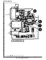
Page 37: ...79 R877 L863 C827 C831 D831 IC871 C872 IC872 L888 L887 C802 R458 R456 R457 R105 R482 R816 R873 R874 SW401 EJECT 1 1 22 22 FROM PICKUP FLEXIBLE PWB P42 1 D 1 1 33 33 FROM AUDIO FLEXIBLE PWB 254 P39 9 H P41 9 H 1 14 FROM KEY FLEXIBLE PWB 231 P42 5 F 1 1 16 16 FROM MECHA FLEXIBLE PWB 8 P42 6 C 1 1 7 7 FROM LCD FLEXIBLE PWB P42 4 H SW402 HOLD 17 9 18 16 2 MAIN PWB A1 BOTTOM 15 14 EXT BATTERY TERMINAL ...

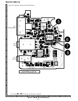
Page 38: ...711 D494 C713 D492 R492 L703 L704 C703 R701 R713 C711 R703 L714 C726 R729 C721 R730 C722 C736 R724 R728 R727 C775 IC771 C774 C773 L771 C772 C734 C725 C731 L710 C710 C733 R503 R502 IC701 R702 R717 C702 C771 R711 R712 R719 R720 C701 C503 C504 R504 L500 R501 C509 C510 R715 C715 C508 C502 C501 C507 C759 C500 1 1 1 12 13 24 12 13 24 12 13 24 R500 R754 L752 C768 R752 C757 C756 R762 IC501 IC703 C755 R714...

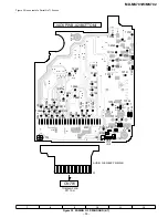
Page 39: ...25 R726 C727 C735 Q721 L772 B TP701 TP728 TP727 TP723 TP724 TP729 TP722 TP721 TP725 TP726 TP702 TP592 TP591 TP709 TP708 TP707 TP585 TP586 TP588 TP590 TP714 TP704 TP703 TP705 TP713TP712 TP593 TP711 TP500 TP576 TP581 TP580 TP578 TP575 TP584 TP582 TP579 TP577 TP574 TP573 TP572 TP571 TP570 TP569 TP568 TP567 TP566 TP565 TP564 TP563 1 1 33 TP562 TP561 Figure 39 is contents to Serial No 712xxxxx ...

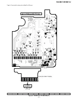
Page 40: ...713 D492 R492 L703 L704 C703 R701 R713 C711 R703 L714 C726 R729 C721 R730 C722 C736 R724 R728 R727 C775 IC771 C774 C773 L771 C772 C734 C725 C731 L710 C710 C733 R503 R502 IC701 R702 R717 C702 C771 R711 R712 R719 R720 C701 C503 C504 R504 L500 R501 C509 C510 R715 C715 C508 C502 C501 C507 C759 C760 C500 1 1 1 12 13 24 12 13 24 12 13 24 R500 R754 L752 C768 R752 C757 C756 R762 IC501 IC703 C755 R714 C753...

Page 41: ...6 C727 C735 Q721 L772 TP701 TP728 TP727 TP723 TP724 TP729 TP722 TP721 TP725 TP726 TP702 TP592 TP591 TP709 TP708 TP707 TP585 TP586 TP588 TP590 TP714 TP704 TP703 TP705 TP713TP712 TP593 TP711 TP500 TP576 TP581 TP580 TP578 TP575 TP584 TP582 TP579 TP577 TP574 TP573 TP572 TP571 TP570 TP569 TP568 TP567 TP566 TP565 TP564 TP563 1 1 33 TP562 TP561 Figure 41 is contents for change from Serial No 801xxxxx ...

Page 42: ... G PICKUP UNIT 15 M902 SLED MOTOR M901 SPINDLE MOTOR M903 LIFT MOTOR SW902 DISC PROTECT MECHA FLEXIBLE PWB UNIT 8 MAGNETIC HEAD FLEXIBLE PWB 23 MAGNETIC HEAD 32 KEY FLEXIBLE PWB UNIT 231 CN101 BK RD SW901 DISC IN TO MAIN PWB P37 10 D CN601 TO MAIN PWB P37 8 D CN451 TO MAIN PWB P37 12 D LCD 232 CN482 ...

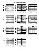
Page 43: ...ngth Smoothiing OFF BW FULL CH1 0 000V CH2 0 00V Main 4K Zoom 4K CH3 0 000V CH4 0 0V Trigger Mode NORMAL Type EDGE CH1 Detay 0 0ns Hold OFF MINIMUM T CK110 HPFO CK108 WBO Stopped CH1 500mV DC 10 1 20us div 20us div CH2 2V DC 10 1 1 2 ENV 16 17 FULL 20MHz Bandwidth ON Smooth OFF 1994 12 18 09 26 46 Filter Offset Record Length Smoothiing OFF BW FULL CH1 0 00V CH2 0 00V Main 10K Zoom 10K CH3 0 00V CH...

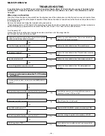
Page 44: ...the bare hand Is the power supply turned on when the remote control button or main unit button is pressed No Perform the check stated in item Power is not turned on when the PLAY button is pressed Perform the check stated in item Abnormal display No Yes Does the display operate normally Is playback state set Yes Perform the check stated in item Playback state connot be set No Is audio output norma...

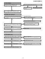
Page 45: ...h reflection disc playback Yes Check between IC401 and CNS482 No Check the periphery of IC401 Does the playback time display advance Yes Position check in INNER mode Check IC201 and IC202 connection line Is the lead in photointerrupter set to OFF when the optical pickup moves to the innermost periphery in NORMAL mode Is TP660 in H level Check the lead in photointerrupter mechanical flex PWB solder...

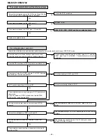
Page 46: ...eck whether disc is record inhibited No Does the RF waveform of TP201 appear when playback is Does level of pins 34 of IC401 and pin 17 of IC101 change depending on record and playback Is RF pattern output from IC201 pin 50 Yes No Check for soldering failure of IC201 No Check periphery of IC401 and IC101 Check whether there is any damage in IC101 periphery of laser diode Yes Check for defects of I...

Page 47: ...31 ANI6 TEMP Input Ambient temperature detection input 32 ANI7 CNTRY Intput Product destination ID input 33 AVSS AVSS Intput A D converter ground potential 34 ANO0 LDVAR Output P U laser power set output 35 ANO1 MDOUT Output Internal motion mode output 36 AVREF1 AVREF1 Output D A converter reference voltage input 37 P70 SYWR Output System LSI write enable output 38 P71 SYRD Output System LSI read ...

Page 48: ... EPCS Output EEPROM chip selection output 81 VDD VDD Output Positive power supply 82 T15 SPIN Inout Spindle motor FG pulse detection input 83 P101 P101 Output Spare for sled motor control 84 P102 TEST0 Input Test mode setting input 0 85 P103 TEST1 Input Test mode setting input 1 86 P30 PSLINN Output Built in battery power selection output 87 P31 PSLDCI Output DC jack power selection output 88 P32 ...

Page 49: ...r type VC MF Cylindrical type without lead wire VC MN Cylindrical type without lead wire VC TV Square type without lead wire VC TQ Square type without lead wire VC CY Square type without lead wire VC CZ Square type without lead wire VC J The 13th character represents capacity difference J 5 K 10 M 20 N 30 C 0 25 pF D 0 5 pF Z 80 20 If there are no indications for the electrolytic capacitors error ...

Page 50: ...licon RB491D D873 VHD1SS372 1 J AD Silicon 1SS372 D875 VHD1SS378 1 J AC Silicon 1SS378 D877 VHD1SS360 1 J AB Silicon 1SS360 PH901 VHPGP1S93K 1 J AF Photo Interrupter GP1S93K COILS L100 VPBNN100M0000 J AC 10 µH L171 RCILC0333AFZZ J AC 10 µH Choke L201 VPBNNR47M0000 J AC 0 47 µH L202 VPBNN100M0000 J AC 10 µH L204 RCILC0353AFZZ J AB Tip Impeder L452 RCILC0352AFZZ J AB Tip Impeder L453 454 RCILC0352AF...

Page 51: ...5 RC KZ1189AFZZ J AC 0 22 µF 16V Electrolytic C877 VCSAFA0JJ106M J AD 10 µF 6 3V Electrolytic Tantalum C878 RC KZ1216AFZZ J AD 3 3 µF 10V Electrolytic C879 RC KZ1193AFZZ J AC 1 µF 6 3V Electrolytic C880 VCKYCY1EB103K J AA 0 01 µF 25V C881 RC KZ1193AFZZ J AC 1 µF 6 3V Electrolytic C886 VCSAFA1AJ106M J AD 10 µF 10V Electrolytic Tantalum C902 VCKYCY1EB103K J AA 0 01 µF 25V C903 RC KZ1216AFZZ J AD 3 3...

Page 52: ...Disc In 8 3 SW902 QSW M0170AFZZ J AD Switch Push Type Disc Protect 8 4 PH901 VHPGP1S93K 1 J AF Photo Interrupter GP1S93K 11 MSPRP0881AFFJ J AB Spring 13 NGERH0596AFZZ J AD Gear Drive 15 RCTRH8175AFZZ J BM Optical Pickup Unit 16 MSPRP0880AFFJ J AC Spring Drive Grip 18 NSFTM0292AFFW J AC Shaft Guide 20 MSPRT1604AFFJ J AB Spring Eject Lever 23 QPWBH0307AFZZ J AF Magnetic Head Flexible PWB 25 MLEVF259...

Page 53: ...BZ0877AFF3 J AA Screw ø1 4 1 5mm 608 LX BZ0805AFFN J AB Screw ø1 7 2 5mm 610 LX BZ0967AFFC J AB Screw PACKING PARTS FOR MD MS701W SPAKA2679AFZZ J AD Packing Add SPAKC6563AFZZ J AL Packing Case SPAKZ0465AFZZ J Pad AC Adaptor SPAKZ0475AFZZ J Pad Operation Manual SPAKZ0475AFZ1 J Pad Operation Manual For Korea SPAKZ0479AFZZ J Sheet SSAKH0314AFZZ J AD Polyethylene Bag Unit ACCESSORIES QCNWG0382AFZZ J A...

Page 54: ... F G H 1 2 3 4 5 6 Figure 5 MD MECHANISM EXPLODED VIEW 5 1 2 7 507 3 6 5 20 4 23 30 509 8 8 1 8 3 SW902 506 501 506 11 13 504 25 26 29 514 15 18 16 505 507 510 512 513 513 M903 M902 M901 28 503x2 502 8 2 SW901 8 4 32 511x2 508 ...

Page 55: ...01 208 211 205 246 213 603 605 215 210 251 606 606 608x2 201 217 217 214 249 250 248 608x2 244 PWB A2 PWB A1 207 206 245 254 202 202 4 202 2 202 1 202 3 227 238 601 606 237 226 232 228 239 237 236 233 234 255 235 240 221 1 241x3 221 3 221 5 242 221 4 221 2 221 234 257 258 231 229 610x2 610 610 610x2 610x2 610 610 253 256 MS702 MS701W ...

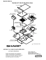
Page 56: ...eplacement Item 7 PACKING OF THE SET MD MS702 ONLY 7 COPYRIGHT 1998 BY SHARP COPORATION ALL RIGHTS RESERVED No part of this publication may be reproduced stored in a retrieval system or transmitted in any from or by any means electronic mechanical photocopying recording or otherwise without prior written permission of the publisher A9801 967 NS HA M SC EX SHARP CORPORATION Audio Visual Systems Gro...

Reviews: