MD-MS722/C/W/MS721W
– 16 –
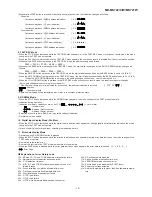
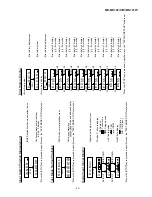
EEPROM (IC402) writing procedure
1. Procedure to replace EE-PROM and write initial value of microcomputer in EEPROM
(1) Replace EEPROM.
(2) Deprive EEPROM of protection (connect the pins 8 and 6 of IC402).
(3) Refer to the latest EEPROM data list.
(4) Press the Display/Lower-case Character button, Enter/Synchro button and Play/Pause button to start the test mode.
(5) Version display
[ V e r . ]
Distination
EEPROM version (C ~ Z)
Microcomputer ROM version
(6) The whole LCD lights.
(7) Test mode stop state
[ T E S T ]
(8) Press the "BASS" button, and press twice the "SKIP DOWN" button.
[ E E P R O M ]
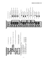
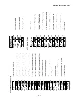
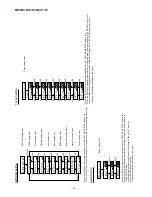
(9) Perform the operation to display "EEPROM SETTING MODE CHART", compare the EEPROM DATA LIST with the display,
and set according to the EEPROM DATA LIST with the VOL UP or VOL DOWN key.
(10) Set the temperature reference. (Refer to the Temperature Reference Setting Method.)
(11) Set according to the EEPROM DATA LIST.
(12) Press the Stop button.
[ T E S T ]
(13) Press the Stop button.
(14) After data is written in EEPROM, turn off power .
(15) Restore protection of EEPROM (Disconnect connection made in Step (2) above).
2. Temperature reference setting method
[1] Measurement, calculation and setting procedure
(1) Set the TEST mode.
•
Set TEST 1, 0 = '01', and turn on power (or set PLAY ON in standby state).
(2) Start the EEPROM mode 'Temp' menu.
•
Key operation in order of BASS, SKIP-DOWN x 2 times, PLAY, PLAY in the test mode STOP state.
•
'TM$$%%' is displayed. ($$= Temperature code, %% = Temperature reference)
(3) Once press SKIP-UP, and determine the displayed microcomputer TEMP input AD value.
• 'TPin##' is displayed. (## = TEMP input AD value)
(4) At the ambient temperature, determine the temperature corrected value from the temperature measurement value
correction table.
(5) Determine the temperature reference, using the following formula.
• Temperature reference = Microcomputer TEMP input AD value + Temperature corrected value
• When data is written into EEPROM, the value shown adove is recorded at the specified address.
[2] Temperature measurement value correction table
Ambient temperature
Temperature correction
- 9
o
C ~ +10
o
C
08h
+ 0.5
o
C
+ 3
o
C ~ +21
o
C
07h
+ 12.5
o
C
+15
o
C ~ +33
o
C
06h
+ 23.6
o
C
+26
o
C ~ +43
o
C
05h
+ 35.0
o
C
Center temperature
[3] Power IC VREF feed control output
•
After automatic adjustment the temperature code is read. If it is within the following range, OK.
Ambient temperature
Temperature correction
+ 9
o
C ~ +11
o
C
- 05h
+ 10.0
o
C
+12
o
C ~ +14
o
C
- 04h
+ 12.7
o
C
+15
o
C ~ +16
o
C
- 03h
+ 15.4
o
C
+17
o
C ~ +19
o
C
- 02h
+ 18.2
o
C
+20
o
C ~ +22
o
C
- 01h
+ 20.9
o
C
+23
o
C ~ +24
o
C
±
00h
+ 23.6
o
C
+25
o
C ~ +27
o
C
+ 01h
+ 26.3
o
C
+28
o
C ~ +30
o
C
+ 02h
+ 29.0
o
C
+31
o
C ~ +33
o
C
+ 03h
+ 31.8
o
C
Center temperature
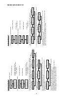
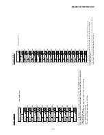
13. INNER Mode
• when the STOP button is pressed on the INNER menu (SQ______ ), the state is changed to the TEST mode STOP state.
• : Address
Summary of Contents for MD-MS721BL
Page 46: ...MD MS722 C WMS721W 46 M E M O ...


