A-2
Appendixes
2.
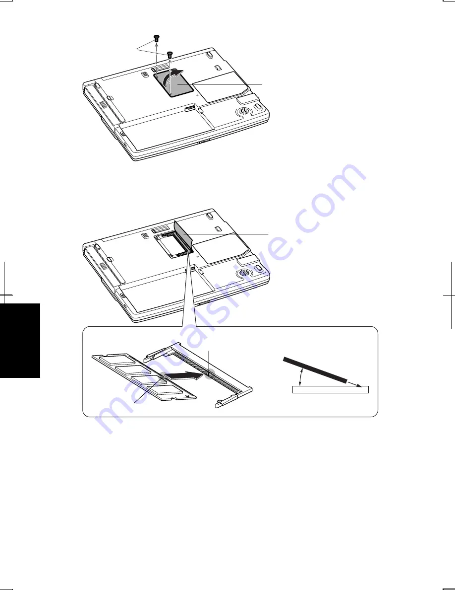
Loosen two screws and remove the memory slot cover.
3.
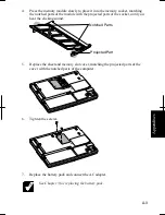
Turn over the sheet and align the memory module as shown below, matching the
notched part of the module with the projected part of the memory socket of the
computer.
Notched Part
Projected Part
20
°
Memory Slot Cover
Screws
Memory Socket
Memory Module
Sheet
Summary of Contents for MV12W - Actius - PIII-M 1 GHz
Page 1: ......
Page 20: ...xix Bottom RESET Battery Pack 3 1 Speaker Reset Switch 2 3 ...
Page 21: ...xx ...
Page 79: ...4 18 4 ...
Page 121: ...Troubleshooting T 12 ...
Page 125: ...Index 2 Index ...
Page 126: ......


