background image


2-8 


2

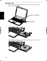
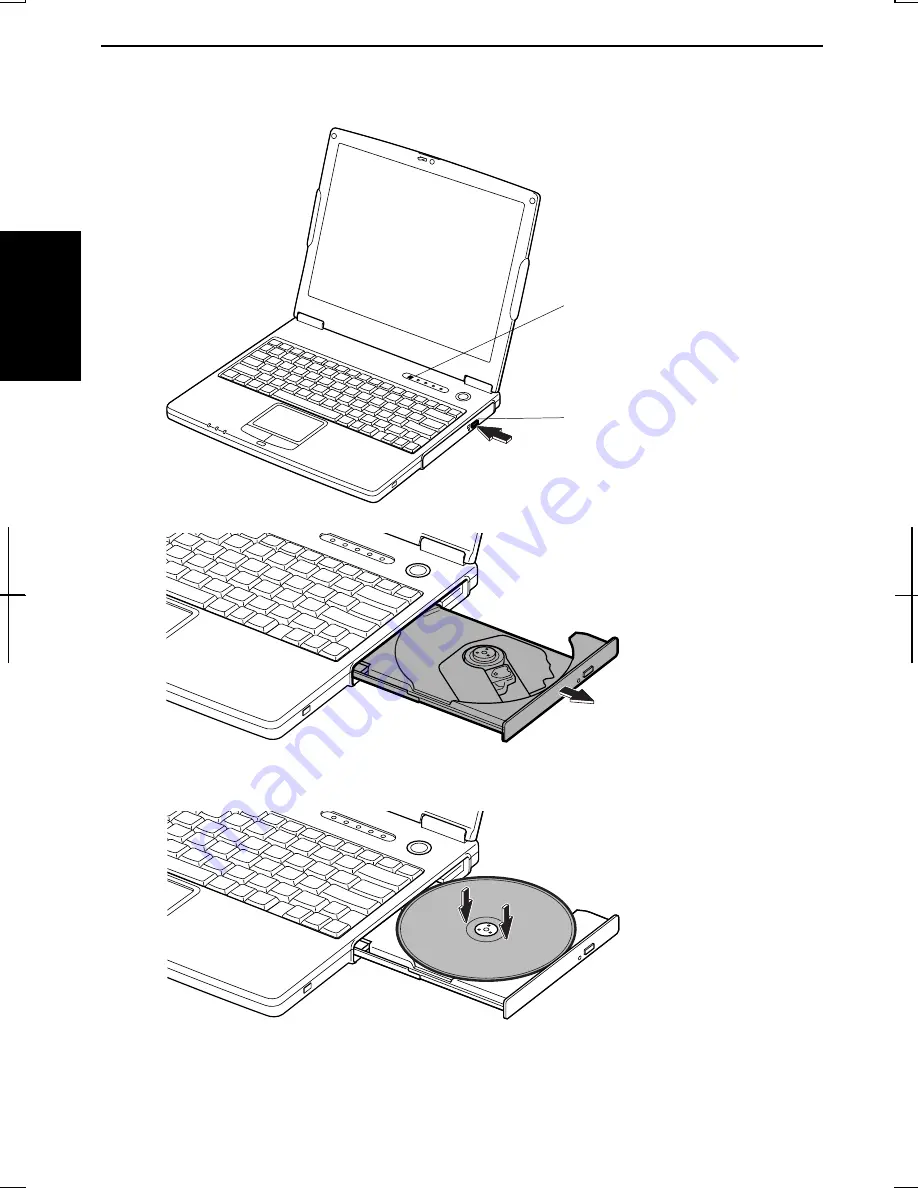
Inserting a Disk 

1. 

Make sure the optical drive indicator is not lit on; then, press the eject button. 
The drive tray opens slightly. 


2. 

Gentry pull out the tray. 


3. 

Place your disk, label side up, onto the tray and slightly press the center of the 
disk until it clicks into the place. 


Optical Drive Indicator 

Eject Button 

Summary of Contents for MV12W - Actius - PIII-M 1 GHz

Page 1: ......

Page 2: ...g the equipment off and on the user is encouraged to try to correct the interference by one or more of the following measures Reorient or relocate the receiving antenna Increase the distance between the equipment and receiver Connect the equipment into an outlet on a circuit different from that to which the receiver is connected Consult the dealer or an experienced radio TV technician for help A s...

Page 3: ...ce notice isn t practical the telephone company will notify the customer as soon as possible Also you will be advised of your right to file a complaint with the FCC if you believe it necessary The telephone company may make changes in its facilities equipment operations or procedures that could affect the operation of the equipment If this happens the telephone company will provide advance notice ...

Page 4: ...ng conditions 1 this device may not cause harmful interference and 2 this device must accept any interference received including interference that may cause undesired operation Warning This product utilizes tin lead solder and fluorescent lamp containing a small amount of mercury Disposal of these materials may be regulated due to environmental considerations For disposal or recycling information ...

Page 5: ...s a serious electric shock may occur To fit an appropriate plug to the mains lead follow the instructions below IMPORTANT The wires in the mains lead are coloured in accordance with the following code Blue Neutral Brown Live As the colours of the wires in the mains lead of this product may not correspond with the coloured markings identifying the terminals in your plug proceed as follows The wire ...

Page 6: ... consent which SHARP is unable to give Please refer particularly to the provisions of the Copyright Act 1956 the Dramatic and Musical Performers Protection Act 1958 the Performers Protection Acts 1963 and 1972 and to any subsequent statutory enactments and orders ...

Page 7: ...ne equipped with a call waiting facility If you attempt to use the modem on a telephone line with call waiting you may experience communication errors To maintain CTR21 network compatibility when used in the above listed countries the following setting should be observed Pulse dial may not be available in some countries Modem Model Name T60M099 Intended Use This is a Personal Computer with Modem f...

Page 8: ...999 5 CE Η συσκευη αυτη ανταττοκρινεται στιζ ατταιτησειζ των οδηγια 1999 5 EK Denna utrustning uppfyller kraven enligt direktiv 1999 5 EC Dette udstyr overholder kravene i direktiv 1999 5 EF Dette produktet oppfyller kravene i direktiv 1999 5 EC Tämä laite täyttää direktiivi 1999 5 EY About the battery Die gebrauchte Lithiumbatterie bitte gegen Kurzschlus sichern z B durch Abkleben der beiden Batt...

Page 9: ...Y VORSICHT UM DIE STROMZUFUHR VOLLSTÄNDIG ZU UNTERBRECHEN DEN NETZSTECKER HERAUSZIEHEN UND DIE BATTERIE ÈNTFERNEN ATTENTION POUR UN ARRET TOTAL DU SYSTEME DECONNECTEZ LA PRISE DE COURANT SECTEUR ET LA BATTERIE VARNING FÖR TOTAL ELEKTRISK URKOPPLING KOPPLA UR KONTAKTEN OCH TA UR BATTERIET PRECAUCION PARA UNA COMPLETA DESCONEXION ELECTRICA DESENCHUFE LA CLAVIJA DE LA RED Y LA BATERIA ...

Page 10: ...ce to an extremely warm place A temperature difference of more than 10 C 18 F will cause condensation inside the unit which may cause damage Do not block or cover slots or openings on the cabinet They protect the computer from overheating Do not place the computer on unstable or uneven work surfaces Do not use the computer on your lap or any part of your body for an extended period during operatio...

Page 11: ...the battery pack in a fire as it could explode and cause injury Do not attempt to open or alter the battery pack Do not place the battery where it might get hotter than 60 C 140 F Do not allow metal objects such as jewelry to short across the battery terminals as it could heat up and explode Do not allow liquids to come in contact with the battery pack Avoid dropping the pack or other violent shoc...

Page 12: ...e telephone line has been disconnected at the network interface Use caution when installing or modifying telephone lines Avoid using the telephone during a lightning storm There may be a remote risk of electric shock from lightning Do not use the telephone to report a gas leak while in the vicinity of the leak Wireless LAN Precautions Do not communicate with wireless LAN in specific environment wh...

Page 13: ...cified battery life has expired or any other causes SHARP assumes no responsibility directly or indirectly for financial losses or claims from third persons resulting from the use of this product and any of its functions such as stolen credit card numbers the loss of or alteration of stored data etc Edition 1st Edition October 2002 Copyright 2002 SHARP Corporation This document contains or refers ...

Page 14: ...re reference please record the following information in the spaces provided below Model Number Serial Number Date of purchase Dealer s Name Place of purchase Password The serial number is printed on a sticker located on the bottom of the computer ...

Page 15: ...dface Press Enter to continue When two or more keys are pressed simultaneously the key labels are separated by a plus sign Restart your computer by pressing Ctrl Alt Delete Sample Entries are shown in lower cases of different typeface c windows system Words Texts on Screen such as window titles or possible parameters are italicized Double click this icon to display the Power Options Properties win...

Page 16: ...ling a Battery Pack 1 1 Connecting to AC Power Source 1 2 Setting Up Windows 1 4 Turning Off the Computer 1 6 Basic Operations Choosing Power Source 2 1 Resetting the System 2 3 Using the Glide Pad 2 4 Using the Keyboard 2 6 Using the Optical Drive 2 7 Writing Data to CD R RW Disks 2 10 Watching DVD ROM Videos 2 11 Controlling Audio 2 15 Adjusting the Display 2 16 Sharing the Computer 2 18 Battery...

Page 17: ...4 IEEE 1394 Device 4 16 Communication Functions Built in Modem 5 1 LAN unit 5 4 Wireless LAN 5 7 Network Setup Utility 5 11 Setup Utility Running the Setup Utility 6 1 Main Menu 6 3 Advanced Menu 6 4 Security Menu 6 5 Boot Menu 6 7 Exit Menu 6 8 Appendixes Memory Module A 1 Installing the Weight Saver A 4 Maintenance and Care A 6 Troubleshooting Index ...

Page 18: ...nt depending on the model Front LCD Screen 2 16 Keyboard 2 6 Glide Pad 2 4 Power Button 1 3 Battery Indicator 2 1 3 3 Power Indicator 2 1 Antenna Indicator which function only for built in wireless LAN model 5 7 Status Indicators A N Hard Disk Num Lock Caps Lock Scroll Lock Optical Drive Antennas which function only for built in wireless LAN model 5 7 ...

Page 19: ...put Jack S PDIF Compliant 4 7 8 9 Microphone Jack 4 10 Ventilation Openings ix USB Ports 4 3 11 15 Optical Drive 2 7 LAN Jack 5 5 IEEE1394 Connector 4 16 Parallel Port 4 15 AC Adapter Jack 1 2 Security Slot A 9 External Monitor Port 4 6 Ventilation Openings ix S Video Output Jack 2 13 ...

Page 20: ...xix Bottom RESET Battery Pack 3 1 Speaker Reset Switch 2 3 ...

Page 21: ...xx ...

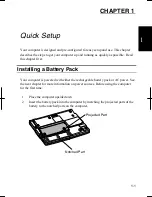
Page 22: ...r first Installing a Battery Pack Your computer is powered with either the rechargeable battery pack or AC power See the next chapter for more information on power sources Before using the computer for the first time 1 Place the computer upside down 2 Insert the battery pack into the computer by matching the projected parts of the battery to the notched parts on the computer Notched Part Projected...

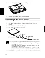
Page 23: ...let Always use the AC adapter included with the computer or the optional one may not be available in some countries Using other AC adapters may damage the computer Always hold the AC power cord by its plug when removing it from the wall outlet Never pull on the cord When using the computer for the first time be sure to operate it on AC power If on battery power instead you may not be able to compl...

Page 24: ...es and raise the cover 5 Press the power button to turn on your computer When you turn on the computer the power indicator turns green the computer goes through a self test to detect any problems and Windows setup process starts See the next page Display Cover Lock Lever Power Indicator ...

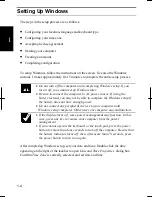
Page 25: ...e able to complete the Windows setup if the battery does not have enough power Do not connect any peripheral devices to your computer until Windows setup completes Otherwise your computer may malfunction If the display turns off some power management may function In this case press any key to resume your computer from the power management If you cannot operate the keyboard or the touch pad press t...

Page 26: ...l Panel There are two types of view for Control Panel One is Category view and the other is Classic view If you select Category view you can choose the category that may be related to what you want to do then choose your task by clicking it If Classic view selected all the icons appear simultaneously Each icon represents its component or feature Double click the icons to open their dialog boxes or...

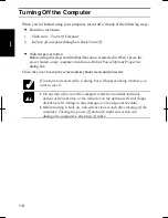
Page 27: ...Options Properties dialog box Close the cover to keep the screen and keyboard clean and protected If you have not saved a file a dialog box will appear asking whether you want to save it Do not turn off or reset the computer while the hard disk indicator optical drive indicator or the indicator on the optional external floppy disk drive is lit Doing so may damage or even wipe out the data Before t...

Page 28: ...mputer You can also use an optional add on battery See Chapter 3 for the battery information About the Power Indicators The following indicators show the power status of your computer Indicator Light Meaning Power On green Operating Blinking green In System Standby Off Powered off or in System Hibernate Battery On green Fully charged On orange Being charged Connected to AC Power Source Blinking or...

Page 29: ...l outlet the AC adapter provides power for operation and charges the battery The AC input voltage can range from 100 to 240 volts so that you can use the computer with the appropriate plug adapter The AC power cord included with the computer is appropriate for the voltage used in the area in which you purchased your computer If you attempt to connect the computer to a wall in other areas check the...

Page 30: ...r dialog box Click Disconnect or Logoff then Yes Resetting may cause data loss Use the resetting process only if the normal Windows Shut Down does not work because of software malfunction Although resetting will not damage the system you may lose the data you are processing Power Switch You can turn off the computer by pressing the power button if you encounter hardware or software problems lockin...

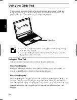
Page 31: ...rectly Using the Glide Pad Take a moment to become familiar with how the glide pad works Place Your Fingertip Place your left or right hand next to the glide pad resting your wrist naturally in a relaxed manner Place your thumb or finger on the glide pad Move Your Fingertip The rectangular pad of the glide pad acts like a miniature duplicate of the display As you slide your fingertip across the pa...

Page 32: ...utton when the object reaches its destination Or you can tap the pad twice instead of pressing the left button in step 2 Scroll You can scroll through information in a list or in a document by using the glide pad To view information vertically place your finger on the most right part of the glide pad and slide your finger up and down To view horizontally place your finger on the bottom part of the...

Page 33: ...ation is sometimes referred to as hot keys Fn F1 Turns the wireless LAN antenna on and off This key combination functions for built in wireless LAN model only and when Wireless LAN of Device Configuration section in Security menu in Setup Utility is set to Enabled Fn F5 Rotates display mode between the LCD only an external monitor only and both when connecting an external monitor Fn F6 Decreases t...

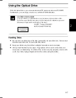
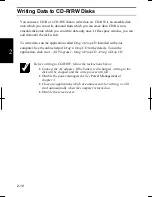
Page 34: ...elength of the laser 144mW 784nm CD R RW 6mW 662nm DVD ROM CLASS1LASER PRODUCT LASER KLASSE1 Handling Disks Do not write on either side of the disk particularly the non label side Data is read from the non label side Do not mark this surface Keep your disks away from direct sunlight heat and excessive moisture Always hold the disks by the edges Fingerprints dirt or water on the disks can cause noi...

Page 35: ...ator is not lit on then press the eject button The drive tray opens slightly 2 Gentry pull out the tray 3 Place your disk label side up onto the tray and slightly press the center of the disk until it clicks into the place Optical Drive Indicator Eject Button ...

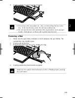
Page 36: ...rface such as paper towels Instead use a cotton swab to gently wipe the lens Removing a Disk 1 Make sure the optical drive indicator is not lit and press the eject button The optical drive tray slightly opens 2 Gently pull out the tray 3 Remove the disk from the tray by holding its edge 4 Gently push the tray back into the computer Make sure the optical drive indicator is not lit or blinking befor...

Page 37: ...g n Drop CD installed with your computer See the online help of Drag n Drop CD for the details To run the application click start All Programs Drag n Drop CD Drag n Drop CD Before writing to CD R RW follow the instructions below Connect the AC adapter If the battery is discharged writing to the disk will be stopped and the write process will fail Disable the power management See Power Management o...

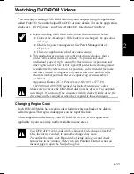
Page 38: ...viewing uses only unless otherwise authorized by Macrovision Corporation Reverse engineering or disassembly is prohibited Apparatus Claims of U S Patent Nos 4 631 603 4 577 216 4 819 098 and 4 907 093 licensed for limited viewing uses only Make sure to remove the DVD ROM disk from the drive when you finish watching it If you turn off the computer with the disk left in the drive the drive may not b...

Page 39: ...on code of your disk is checked in the right box If you want to change the drive code and play your disk click OK On some DVD ROM disks plural region codes are selectable in their right box of Confirm Region dialog box Carefully choose an appropriate code Using Parental Control If you want to set the parental control to prevent your children from watching an inappropriate movie follow the steps be...

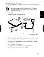
Page 40: ...levision set to your computer 3 Turn on the computer and the television set 4 Right click somewhere on the Windows desktop and click Properties from the pop up menu Display Properties dialog box opens 5 Click Settings tab Advanced button Intel Graphic Technology tab then Graphic Properties button 6 Select TV and click OK three times 7 If you can see the screen image on the television set click Yes...

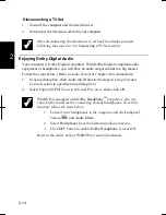
Page 41: ...eps below Refer to Audio System of Chapter 4 for connection 1 In Setup dialog box click Audio tab Refer to the steps in Using Parental Control section to open the Setup dialog box 2 Select Digital S PDIF out to External Processor then click OK WinDVD is equipped with Dolby HeadphoneTM properties You can enjoy Dolby sound just by connecting normal headphones To set this function follow the steps be...

Page 42: ...s and Audio Devices icon 3 In Sounds and Audio Devices Properties dialog box slide the lever to control the output volume 4 Click OK and close the dialog box then the Control Panel window Check the box of Place volume icon in the taskbar in the step 3 above Next time you find the speaker symbol on the taskbar and it is easy to control volume If you want to control the output volume of each source ...

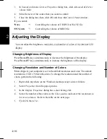
Page 43: ...ys simultaneously to decrease the brightness of the display Press Fn and F7 keys simultaneously to increase the brightness of the display Changing Resolution and Number of Colors When shipped your computer is set to the default resolution and color The default resolution is 1024 x 768 at 64K colors To change the resolution and the number of colors perform the following 1 Right click anywhere on th...

Page 44: ...of colors in this mode is made using a dithering algorithm You cannot switch to a display resolution and number of colors that are not available In the Color Quality Medium 16 bit means 65 536 64K colors and Highest 32 bit means about 16 770 000 16M colors If you select Highest Drawing speed may be delayed When playing animation the screen may be distorted Changing Wallpaper and Setting Screen Sav...

Page 45: ...l Panel window If more than one user accounts are set to the computer you must select which user account you will log in when you turn on the computer Log off the Computer Log off is useful because you do not have to turn off the computer when you finish your task and pass the computer to another person There are two ways to log off the computer Switch User and Log Off If you select Switch User yo...

Page 46: ...ption if you log onto the computer as a member of the Computer administrators group If you log on the computer with a limited user account go to the next step You cannot set a password to another user account 4 Select Create a password string If the password has been already set Create a password will not appear Only the members of the Computer administrators group can set a password to another us...

Page 47: ...1 2 on Setting Password section 2 Select the account you want to delete its password if you log on to the computer as the members of the Computer administrators group If you log on the computer with a limited account go to the next step You cannot delete the password of another user account 3 Select Remove the password string or Remove my password string If the password has not been set yet Remove...

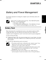
Page 48: ...gement is active See the next section for power management To keep the battery life long Condition the battery pack if the actual remaining power in your battery is less than what Windows Power Meter indicates See Conditioning the Battery Pack section in this chapter Turn off your computer when you are not using it The duration of the battery will depend on the computer usage Using applications wh...

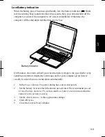
Page 49: ...ssistance When the battery pack is hot for example after a long usage it may take longer to be fully charged Checking the Battery Level You can check the battery level by pointing to the battery or AC plug icon on the taskbar or double clicking the icon to open the Power Meter dialog box If the battery is fully charged remaining capacity level will not appear even if you point the icon If you cann...

Page 50: ...u when the battery drops to the specified level by sounding an alarm or displaying a message and let your computer go on System standby System hibernate or shut down automatically 1 In the Power Options Properties dialog box select Alarms tab 2 Set the battery level at which the alarms are activated We recommend you set Critical battery alarm to 5 or more and Low battery alarm to more than the val...

Page 51: ...til the battery is completely discharged and the system shuts down automatically 5 Connect the computer to AC power and let the battery fully charged again 6 Restart the computer The conditioning process completes Do not connect the computer to wall outlet while discharging the battery The conditioning will be cancelled Changing the Battery Pack The capacity of a battery pack gradually decreases w...

Page 52: ... and hold it then pull out the battery pack 4 Insert a new battery pack into the computer by matching the projected parts of the battery with the notched parts on the computer 5 Push the battery pack until you hear the clicking sound 6 Turn over the computer and it s ready to use Battery Stopper Notched Part Battery Release Lever Projected Part ...

Page 53: ...e countries Never attach any add on batteries but the optional ones CE BL20 Attaching an Add on Battery Pack Follow the steps below 1 Turn off the computer and disconnect the AC adapter from the computer 2 Close the display cover and turn over the computer on a flat place 3 Open the cover of the add on battery pack socket on the bottom of the computer Cover ...

Page 54: ...wn the battery pack 6 Slightly press the two levers of the battery pack inwards and hold them then press down the battery pack and release the levers Make sure each of the triangle logos on each of the battery pack go with the line marks of the computer Notched Part Projected Part Levers Triangle Logo Line Mark ...

Page 55: ...er the computer on a flat place 3 Slightly press the two levers of the battery pack inwards and hold them 4 Slightly lift up the front of the battery pack and release the levers Make sure to lift up the battery pack softly and slightly Lifting it up with excessive force may cause the projections of the battery damaged 5 Push out the battery backward and remove it Levers ...

Page 56: ...Battery You can check the add on battery level with one of the following ways On Windows Refer to Checking the Battery Level section in this chapter With the battery level lamp When you press the battery level button the battery level lamps light up Conditioning an Add on Battery Pack 1 Connect the add on battery pack 2 Refer to Conditioning the Battery Pack in this chapter Cover Battery Level But...

Page 57: ...w is selected double click Power Options icon Note that the power management may not seem to function when you are using an application program that accesses the hard disk periodically Stopping Power Supply to the Hard Disk 1 In Power Options Properties dialog box select Power Schemes tab 2 Set Turn off hard disks to an appropriate value and click OK 3 Close the Control Panel window Stopping Power...

Page 58: ...ate Home Office Desk Using Battery Performance state will be chosen based on CPU demand Using AC Power Performance state will be chosen based on CPU demand Portable Laptop Using Battery Performance state will be chosen based on CPU demand Using AC Power Performance state will be chosen based on CPU demand Presentation Using Battery Uses liner performance reduction as the battery discharges Using A...

Page 59: ...o all but a few essential components Your system enters and resumes from System standby per the conditions mentioned later In System standby the power indicator or the battery power indicator blinks green To resume from System standby operate the computer again System hibernate saves the current condition of the computer in an area of the hard disk and turns off the computer Your system enters and...

Page 60: ... the Power Options Properties dialog box select Power Schemes tab 2 From the pull down menus in System standby or and System hibernate select the time after which the computer will enter System standby System hibernate 3 Click OK then close the Control Panel window Entering System Standby Hibernate Your computer enters System standby System hibernate in each of the following cases You select Stand...

Page 61: ...y computer 3 Click OK then close the Control Panel window If Ask me what to do is selected in the step 2 of You press the power button or You press Fn Fn12 the Turn off computer dialog box will appear when you press the power button or Fn F12 key combination You can select System standby or System hibernate at that timing The battery level is low The above functions if you set the alarm in Windows...

Page 62: ...e peripheral devices shown on the next page For the details refer to the section explaining each device or contact your dealer Be sure to turn off the computer and the peripheral device before connecting them except when connecting USB devices IEEE 1394 devices or inserting a PC card Confirm the peripheral device you will connect is Windows XP compatible Some devices have to be turned on after the...

Page 63: ...4 2 4 Peripheral Connection Overview Video Equipment with S video USB Devices Headphone Audio Equipment Microphone External Monitor IEEE 1394 Device Printer PC Card ...

Page 64: ... the floppy disk drive unit It may cause the drive to malfunction Connect the floppy disk drive unit cable to either of the USB ports on the computer Be sure to let the USB mark side up when connecting the cable to the computer Handling Floppy Disks Do not open the shutter and touch the disk inside otherwise you will not be able to read or write data from to the disk Do not place floppy disks near...

Page 65: ...orce when inserting the floppy disk If you have difficulty inserting or removing disks seek the assistance of an authorized service technician Do not touch the disk while reading writing data It may cause malfunction of the computer and the drive Ejecting a Floppy Disk Before ejecting the floppy disk make sure the indicator of the floppy disk drive unit is not lit Press the eject button firmly The...

Page 66: ...form the following steps before you remove it 1 Click Safely Remove Hardware icon on the taskbar If you cannot find the icon click to show all kinds of icons 2 Click on Safely Remove Mitsumi USB Floppy Drive A string Safe To Remove Hardware dialog appears 3 Remove the unit from the computer Display You can use an external monitor with your computer To display the same images on both displays simul...

Page 67: ...ternal monitor 5 Turn on the external monitor then the computer Disconnecting an External Monitor 1 Turn off the computer and the external monitor 2 Loosen the screws of the monitor cable if it has and remove the cable from the computer and the monitor Displaying on an External Monitor To display the image on an external monitor you may need to install the driver for the external monitor Before us...

Page 68: ...with Fn F5 While playing video or animation you may not be able to switch the display The screen may be distorted when you switch the display When it occurs refresh the screen by right clicking on the Windows desktop and clicking Refresh in the pop up menu Audio System You can output sound to speakers audio equipment or a headphone Connecting Speakers You can connect stereo speakers with an amplif...

Page 69: ...ipment Connect AC adapter to the digital audio equipment Exit other application programs Disable Windows power management Do not enter System standby System hibernate Do not operate the computer Use the digital audio equipment compliant to sampling rate of 48kHz Sound may not be recorded correctly if you use the synchronized recording system of the digital audio equipment S PDIF Compliant Audio Eq...

Page 70: ...volume on Windows by double clicking the speaker symbol in the taskbar Connecting a Headphone Use the headphone with an impedance of more than 8Ω 32Ω is recommended Audio Output Jack White L Red R Audio Output Jack Analog Audio Cable Stereo Mini Plug Stereo Mini Plug ...

Page 71: ...the microphone jack Use an electret condenser microphone with an impedance of 2 2kΩ and an allowable voltage of 2V To record sound 1 Click start then point All Programs Accessories Entertainment 2 Click Sound Recorder 3 See Help for Sound Recorder for more information Microphone Jack Mini Plug ...

Page 72: ...priate driver is automatically installed If the driver is not installed correctly you will see a message on the screen In this case install the driver by following the instructions on the screen To remove USB devices you may need to perform the following instructions before you remove them 1 Click Safely Remove Hardware icon on the taskbar If you cannot find the icon click to show all kinds of ico...

Page 73: ...r to its manual Inserting a PC Card When a new card is correctly inserted the appropriate driver is automatically installed If the driver is not installed correctly you will see a message on the screen In this case install the PC card driver by following the instructions on the screen 1 Confirm the PC card eject button is inside the computer cabinet If the button is not inside the computer cabinet...

Page 74: ...ong use Be sure to use the procedure below when ejecting a PC card Otherwise the system may not work properly 1 Click the Safely Remove Hardware icon on the taskbar If you cannot find the icon click to show all kinds of icons 2 Click on Safely remove xxxxx string xxxx is the name of your PC card then Safe To Remove Hardware dialog appears 3 Push the PC card eject button so that it pops out from th...

Page 75: ...ded parallel cable adapter CE PP01 or either of the USB ports Before using a printer read the printer manual and install the printer driver Connecting to the Parallel Port 1 Turn off the computer and the printer 2 Connect the parallel cable adapter and the printer cable If it has screws make sure to tighten them 3 Open the cover for the parallel port on the rear side of the computer Cover Parallel...

Page 76: ... the cover after you finish using the parallel port Connecting to the USB Port Be sure to read the printer manual before connecting the USB printer to the computer Some printer may not use New Hardware Find wizard to install the printer driver You can connect the USB printer to the computer without turning off the computer Printer Cable Parallel Cable Adapter Parallel Port USB Port ...

Page 77: ...ible with not only the equipment that is directly connected but also with other devices via the directly connected device Confirm the IEEE 1394 device you will connect is Windows XP compatible Some IEEE 1394 devices require that you install drivers before use Use AC power for the computer especially when reading writing the data Connecting an IEEE 1394 Device You need not turn off the computer bef...

Page 78: ...ate application for handling your data Disconnecting an IEEE 1394 Device 1 Click the Safely Remove Hardware icon on the taskbar If you cannot find the icon click to show all kinds of icon If the icon does not appear go to Step 3 2 If the name of your device appears click on Safely remove xxxxx string xxxxx is the name of your IEEE 1394 device then Safe To Remove Hardware dialog appears 3 Remove th...

Page 79: ...4 18 4 ...

Page 80: ... terminal or a digital PBX Use TA terminal adapter to connect the built in modem to a digital telephone line If an unusual device is attached to the line you are connecting to the modem may not function properly Remove the device or contact the dealer of the device Before connecting to a PBX consult the PBX maintenance staff or its service company If the electric characteristics of your PBX are di...

Page 81: ...er after you finish using the built in modem 3 Connect one end of the included modem cable to the modem jack and the other to the telephone line Do not insert the modem cable into the LAN jack It may damage the LAN jack and the modem cable 4 Turn on the computer Connect the modem to the telephone line directly Do not use a distributor or allotter Modem Jack To Telephone Line Modem Cover ...

Page 82: ...ng Rules tab for the information you set above You can change the settings or make a new location by clicking Edit or New Internet Connection Windows XP has a special Internet connection wizard to help you to connect to the Internet with ease 1 Click start Control Panel Network and Internet Connections then Network Connections If Classic view is selected double click Network Connections icon 2 In ...

Page 83: ...r infrastructure Before commencing with fax communication it is recommended that you exit other application programs LAN unit You can connect to a LAN Local Area Network with the 100 Base TX 10 Base T LAN unit on your computer To activate the LAN unit perform the following steps Use a category 3 or a category 5 LAN cable when connecting to 10 BASE T LAN and the category 5 only when connecting to 1...

Page 84: ...u finish using the LAN unit 5 Connect the core end of the LAN cable to the LAN jack and the other end of the LAN cable to the network hub Do not connect the LAN cable to the modem jack next to the LAN jack It will damage the LAN cable and the modem jack 6 Turn on the computer LAN Jack LAN Jack Cover LAN Jack Core LAN Cable To Network Hub ...

Page 85: ... cable always use that LAN cable If your LAN cable has no core attached please attach the provided core before use Make sure to log on the computer as a member of the Computer administrators group Otherwise you cannot set or change some settings for the LAN unit If you cannot access the network 1 Click start Control Panel 2 Click Performance and Maintenance then System If Classic view is selected ...

Page 86: ... equipped with wireless networking interface Each computer can communicate directly with other wireless enabled computers The range to give reliable performance and the quality of connection vary depending on the environment where you perform To communicate through the wireless LAN activate the integrated antennas with the following steps Activate Antennas You can enable disable the antennas by pr...

Page 87: ...nection of Network Tasks 4 Double click on Internet Protocol TCP IP string in This connection uses the following items 5 In Internet Protocol TCP IP Properties dialog box select Use the following IP address and set a unique IP address to 192 168 1 2 through 192 168 1 254 and the Subnet mask to 255 255 255 0 then click OK The IP address of each computer should be unique The Default gateway can be b...

Page 88: ...n the network name you want to access does not appear click Advanced tab then Refresh button of Available networks in Wireless Network Connection Properties dialog box then click OK 3 Click Wireless Network Connection icon on the taskbar 4 In Wireless Network Connection Status dialog box confirm your connection status The number of green signals shows the connection The more signals light on the b...

Page 89: ... following steps Note that some access points have the key index options 1 through 4 Refer to the table below for matching 1 Open the Wireless Network Connection Properties dialog box Refer to the steps in Communicating with Other Computer section 2 Select the network you want to access in Preferred networks section and click Properties button 3 Confirm the box of Data encryption WEP enabled is ch...

Page 90: ...urrent environment and follow the instructions below 1 Click start All Programs SHARP Network Setup Utility SHARP Network Setup Utility 2 Click OK 3 Click Set select SHARP icon or Windows icon and then click Select icon button 4 Select an icon and click OK Type a network name then click OK The selected icon appears in the Network Setup Utility window It takes a moment to load the network settings ...

Page 91: ...the settings Changing Network Settings To change the loaded network settings right click on the icon you want to change the settings in the Network Setup Utility window and click Edit settings in the pop up menu Then edit the settings Deleting Network To delete the loaded network settings right click on the icon you want to delete in the Network Setup Utility window and click Delete setting in the...

Page 92: ...ed in a special area called CMOS RAM which the system reads every time you turn on the computer Your computer is shipped from the factory with the appropriate setting of the Setup Utility Leave it as default in normal use Contents of the Setup Utility The Setup Utility consists of five menu pages as follows Main Configures basic setting Advanced Configures device interface I O ports etc Security S...

Page 93: ...o not close the display cover Changing the Setting of the Setup Utility To change the settings 1 Use or key to select the menu then press Enter 2 Use or key to select the item On item with mark press Enter to open its sub menu Press Esc to close the sub menu and return to the previous menu Most of the items without mark can be changed their values or status by pressing Enter when selected For date...

Page 94: ... be numlocked if connected USB key Mouse Emulation defines whether USB devices keyboard or mouse can be used in MS DOS mode Quick Boot defines whether the system skips the check of the internal memory while booting to shorten the boot time Quiet Boot defines whether the SHARP logo appears on the screen while booting Video RAM Size shows the minimum size of the video memory In Windows environment t...

Page 95: ...PP Enhanced Parallel Port mode or Output only Disabled means that you cannot use the port Internal Pointing Device enables or disables the built in glide pad Resolution Expansion defines whether the Setup Utility screen is expanded when the resolution is 640x480 or 800x600 Enabled means that the screen is expanded Plug Play O S enables or disables plug play function Normally this option has to be ...

Page 96: ...re set to Normal Device Configuration enables and disables built in devices such as USB audio system modem LAN PC card IEEE1394 and Wireless LAN Supervisor and User Password Setting a password will protect your computer against unauthorized access Once a password is set the system requires the password when entering to the Setup Utility And if Password on boot is enabled the system will require a ...

Page 97: ...d 1 In the Security menu of the Setup Utility select Set Supervisor Password or Set User Password and press Enter 2 Type your current password and press Enter 3 Type your new password and press Enter 4 Type your new password again and press Enter twice 5 Select Exit menu and confirm Exit Saving Changes is highlighted then press Enter 6 Confirm Yes is highlighted and press Enter The system restarts...

Page 98: ...ppy disk drive When you set Auto or Enabled the system boots according to the order set in the Boot Sequence field When you set Disabled the system does not boot from the USB floppy disk drive Auto allows you to use the floppy disk drive only when you boot the system from a floppy disk or with a CD or a hard disk each formatted in an operating system supporting USB LAN Boot defines whether the sys...

Page 99: ...ut saving the settings you have changed Load Setup Defaults returns the values of all items to the default To exit select one of the above items Discard Changes returns the values of all items to the values you last saved To exit select one of the above two items Save Changes saves the settings you have changed To exit select one of the above two items ...

Page 100: ...ily generated such as on the carpet Before installing the memory module carefully discharge static electricity from your body by touching an unpainted metal area Avoid touching the integrated circuits on a memory module Handle all components by the edges Keep the memory module in the anti static wrapping until you are ready to install it 1 Turn off the computer and disconnect the AC adapter and re...

Page 101: ... cover 3 Turn over the sheet and align the memory module as shown below matching the notched part of the module with the projected part of the memory socket of the computer Notched Part Projected Part 20 Memory Slot Cover Screws Memory Socket Memory Module Sheet ...

Page 102: ...projected parts of the socket until you hear the clicking sound 5 Replace the sheet and memory slot cover matching the projected parts of the cover with the notched parts of the computer 6 Tighten the screws 7 Replace the battery pack and connect the AC adapter See Chapter 3 for replacing the battery pack Notched Parts Projected Part ...

Page 103: ... follow steps 5 8 of Installing a Memory Module Installing the Weight Saver You can change the optical drive unit for the weight saver to make your computer lighter With the weight saver installed instead of the optical drive unit you can get the better portability Always keep the optical drive bay installed either of the optical drive unit or the weight saver Leaving the optical drive bay empty m...

Page 104: ...l it clicks Re installing the Optical Drive Unit 1 Turn off the computer and disconnect the AC adapter from the computer Make sure to turn off your computer and remove the AC adapter Otherwise the computer may be damaged 2 Close the display cover and turn over the computer on a flat place 3 Slide the optical drive stopper backward and pull out the weight saver from the computer Optical Drive Stopp...

Page 105: ...ng the information of the Setup Utility etc If you see the message Press F1 to resume F2 to Setup replace it with a Lithium CR2032 Battery on the market 1 Turn off the computer disconnect the AC adapter and remove the battery pack from the computer Make sure to turn off your computer and remove the AC adapter and the battery pack from your computer Otherwise the computer may malfunction 2 Loosen t...

Page 106: ...uter may malfunction 4 Insert a new backup battery with the plus side printed a part number up Press two hooks of the box with the edge of the battery and hold it then press down the battery 5 Replace the cover on the computer matching the projected parts of the cover with the notched parts of the computer Hooks Notched Parts Projected Parts ...

Page 107: ...ts then press Enter 12 When the message Load default configuration now appears select Yes then press Enter 13 In the Exit menu select Exit Saving Changes then press Enter 14 When the message Save configuration changed and exit now appears select Yes then press Enter 15 Click start Control Panel 16 Click Date Time Language and Regional Options in Category view then click on Change the date and time...

Page 108: ... to prevent theft Cleaning the Computer Cabinet Apply a small amount of mild cleaning solution to a dry lint free cloth and wipe the cabinet with the cloth Never clean the computer while it is powered on Do not use alcohol benzene thinner or other strong chemical agents that may damage the cabinet Security Cable Security Slot ...

Page 109: ...raveling please follow these guidelines Before traveling back up your data onto floppy disks optical disks or other external media Do not travel with any peripherals such as an external floppy disk drive unit or the parallel cable adapter connected Do not carry the computer powered on This may result in loss of data and or damage to the hard disk drive Make sure the display cover is properly close...

Page 110: ...e capable of generating errors and error messages If you encounter a software error try to determine if the error message is from your operating system or from an application program and refer to the appropriate manual for possible remedies You can also refer to the Windows manual or Windows help program to solve the problem To access the help program click start Help and Support It also gives you...

Page 111: ... either a defective disk or one without an installed operating system Remove the disk Question Why can t I boot from the floppy disk Make sure that the external floppy disk drive unit is correctly connected to the computer Check whether the floppy disk set to the external floppy disk drive unit contains a system disk Open the Setup Utility window and confirm that USB of Device Configuration in Sec...

Page 112: ... by pressing Fn F11 If you still have the problem after trying the above follow the steps in Why doesn t the keyboard or the glide pad function Question Why does the external monitor display nothing or the image on it distorted Confirm the monitor is turned on Confirm the monitor is connected correctly Make sure an external monitor is selected as the display by pressing Fn F5 If you use Fn F5 to c...

Page 113: ... F5 keys When playing the animation or game Fn F5 key combination may not work Close the currently running application Use Display Properties dialog box to change it When connecting to a TV set Fn F5 key combination does not work When you select Extended Desktop mode Fn F5 key combination does not work Trouble with Keyboard Glide Pad Question Why doesn t the keyboard or the glide pad function Try ...

Page 114: ...you cannot use the USB floppy disk drive Set the USB FDD to Enabled in Boot menu of the Setup Utility If you cannot write to a floppy disk the disk may be write protected Eject the disk and ensure that the write protect tab covers the detection hole If you cannot write to a floppy disk the disk may be full Use another disk Trouble with the Hard Disk Question Why can t I read or write data to from ...

Page 115: ... DVD movie play smoothly Ensure to use AC power Set back the screen resolution color quality and screen refresh rate to the default value See the specifications on the supplement for the default values of your computer Question Why isn t the optical drive recognized If the computer is turned on with some kinds of DVD disks inserted in the drive the drive may not be recognized In this case turn off...

Page 116: ...nection Wizard check Use dialing rules in the Properties dialog box of that connection status Refer to Internet Connection section of Chapter 5 Confirm the country region setting is appropriate Confirm the network configuration is appropriate Confirm the user name or password is correct Confirm the COM port in the communication software is set appropriately Turn off the power management in the Win...

Page 117: ...ss LAN communication Confirm the access point is powered on Restart your computer Confirm your computer is enabled for the wireless LAN Detect the access point by following the steps below 1 Click start My Computer 2 Select My Network Places in Other Places field then View network connections in Network Tasks field Network Connections dialog box appears 3 Right click Wireless Network Connection th...

Page 118: ... of each computer To open Advanced dialog box refer to Communicating with Other Computers section of Chapter 5 Adjust the distance between the computers by bringing your computer closer to others and remove any obstructions that may impede the communication then try to connect again The distance between computers or access points should be less than approximately 60 m 190 feet in the direct line o...

Page 119: ...et Turn off hard disks to Never Confirm they are Windows XP compliant Confirm drivers necessary for the devices are installed Other Troubles Question Why is the battery pack discharged so quickly Initialize the battery pack Question Why is the date and or time incorrect Correct the date and time in Windows Double click the time appearing on the taskbar and set them in Date and Time Properties dial...

Page 120: ...y can t I record the sound from the microphone Follow the instructions below 1 Double click the speaker symbol on the taskbar 2 Click Options and select Properties 3 Select Recording in Adjust volume and confirm Microphone is checked in Show the following volume controls then click OK 4 Confirm Select is checked in Microphone of Recording Control dialog box 5 Close the Recording Control dialog box...

Page 121: ...Troubleshooting T 12 ...

Page 122: ...ery indication 3 3 C Cleaning computer A 9 CD handling 2 7 inserting 2 8 removing 2 9 troubleshooting T 5 CD R RW 2 10 D Display changing brightness 2 16 changing resolution 2 16 changing number of colors 2 16 switching the display 2 6 4 7 troubleshooting T 3 turning off 2 6 DVD ROM parental control 2 12 playing 2 13 region code 2 11 troubleshooting T 6 E Encryption key 5 9 External monitor connec...

Page 123: ... troubleshooting T 7 N Network setup utility changing 5 12 deleting 5 12 loading 5 11 switching 5 11 O Optical drive troubleshooting T 5 P Passwords changing 2 19 6 6 deleting 2 20 6 6 setting 2 19 6 6 PC cards ejecting 4 13 inserting 4 12 Peripherals audio equipment 4 7 connecting guidelines 4 1 external floppy disk drive 4 3 external monitor 4 5 headphones 4 9 IEEE 1394 device 4 16 microphone 4 ...

Page 124: ...ing 3 13 System standby about 3 12 generating conditions 3 13 resuming from 3 12 T Television set 2 13 Troubleshooting common problems T 1 communications T 7 display T 3 external floppy disk drive T 5 hard disk drive T 5 keyboard or glide pad T 4 LAN T 8 optical drive T 5 peripherals T 9 wireless LAN T 8 U USB device 4 11 W Wallpaper 2 17 Weight saver A 4 WEP key 5 9 Windows XP first time setup 1 ...

Page 125: ...Index 2 Index ...

Page 126: ......

Reviews: