MX-LCX5 REPLACEMENT AND ADJUSTMENT 3 – 6
Normally the side registration of the image can be adjusted in the
SP mode.
If the punch hole positions are not aligned from a particular feed
station, however, you can manually adjust the side registration by
changing the tray cover position for that tray, and then adjust the
side registration of the image.
1)
Pull out the tray.
2)
Change the screw positions [A] at both the right and left sides
as shown.
NOTE: Adjustment range: 0
±
2.0 mm adjustment step: 1.0 mm/
step
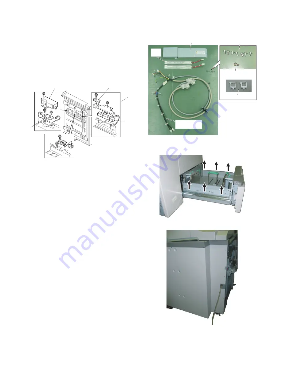
11. Image position board and sensor
Image Position Sensor
• Disconnect the LCT from the copier.
[A] Image position sensor unit (screw x 2, connector x 1)
[B] Stopper (screw x 1)
[C] Image position sensor
• After replacing the image position sensor do the procedure for
image position sensor adjustment. (see 12.)
Image Position Sensor Board
• Disconnect the LCT from the copier.
[D] Cover (screw x 2, clamp x 2)
[E] Image position sensor board (screw x 2, connector x 2, clamp x
2)
12. Dehumidifier heater installing
procedures (0PQC4180431//)
A. Component parts
B. Installing procedures
1)
Remove the lower-stage cassette. (6 screws)
2)
Remove the rear cabinet. (6 screws)
[A]
[B]
[
C
]
[
E
]
[
D
]
Interface harness
(with heater line)
M4 washer screw
(x 1)
M4 screw (x 7)
Heater cover
Clamp (x 2)
Heater
(x 2)
Summary of Contents for MX-LCX5
Page 24: ...Memo ...
Page 25: ...Memo ...


