INSTALLATION MANUAL FOR PHOTOVOLTAIC MODULES
ELECTRICAL OUTPUT AND THERMAL CHARACTERISTICS
Rated electrical characteristics are within ±10 percent of the indicated values of Isc, Voc, and +10/-5 percent of Pmax under STC (standard test
conditions) (irradiance of 1000 W/m
2
, AM 1.5 spectrum, and a cell temperature of 25°C (77°F). The warranty conditions are specified elsewhere in
this manual.
PLEASE READ THIS MANUAL CAREFULLY BEFORE USING THE MODULE
IMPORTANT SAFETY INSTRUCTIONS
This manual contains important safety instructions for the PV module that must be followed during the maintenance of PV modules.
To reduce the risk of electric shock, do not perform any servicing unless you are qualified to do so.
1. The installation must be performed by a certified installer/servicer to ensure system integrity and safety.
2. The installation is only allowed after referring and understanding of GENERAL INSTALLATION MANUAL and INSTALLATION MANUAL
-PHOTOVOLTAIC MODULE-. If you don’t have your personal copy, please contact your installer or local Sharp office listed in Sharp
Solar web site : URL : http://www.sharp-world.com/solar
3. Do not pull the PV cables.
4. Do not touch any surface of module.
5. Do not place/drop objects onto the PV modules.
6. Do not disassemble or attempt to repair the PV module by yourself.
7. Do not drop the PV module.
8. Do not damage, pull, bend, or place heavy material on cables.
9. Upon completion of any service or repairs, ask the installer/servicer to perform routine checks to determine that the PV modules are in
safe and proper operating condition.
10. When replacement parts are required, be sure the installer/servicer uses parts specified by the manufacturer with same characteristics
as the original parts. Unauthorized substitutions may result in fire, electric shock, or other hazard.
11. Consult your local building and safety department for required permits and applicable regulations.
C
CA
AU
UTTIIO
ON
N:: H
HIIG
GH
H V
VO
OLLTTA
AG
GE
E
TToo rreedduuccee tthhee rriisskk ooff eelleeccttrriicc sshhoocckk,, ddoo nnoott ttoouucchh..
Under normal conditions, a photovoltaic module is likely to experience conditions that produce more current and/or voltage than reported at Stan-
dard Test Conditions. Accordingly, the values of Isc and Voc marked on this module should be multiplied by a factor of 1.25 when determining com-
ponent voltage ratings, conductor capacities, fuse sizes and size of controls connected to the module output.
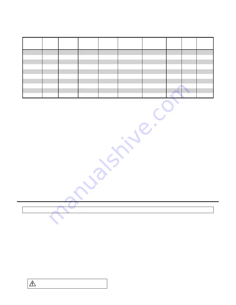
M
Maaxxiim
muum
m
TToolleerraannccee
O
Oppeenn--C
Ciirrccuuiitt S
Shhoorrtt--C
Ciirrccuuiitt
V
Voollttaaggee aatt P
Pooiinntt
C
Cuurrrreenntt aatt P
Pooiinntt M
Maaxxiim
muum
m
O
Ovveerr--
A
Apppplliiccaattiioonn
P
Poow
weerr
V
Voollttaaggee
C
Cuurrrreenntt
ooff M
Maaxx.. P
Poow
weerr
ooff M
Maaxx.. P
Poow
weerr
S
Syysstteem
m
C
Cuurrrreenntt
C
Cllaassss
((P
Pm
maaxx))
((V
Voocc))
((IIsscc))
((V
Vm
mpppp))
((IIm
mpppp))
V
Voollttaaggee
P
Prrootteeccttiioonn
N
ND
D--115588E
E11FF
158.0W
+10% / -5%
28.6V
7.92A
22.5V
7.03A
1000V
15A
A
N
ND
D--116622E
E11D
D
162.0W
+10% / -5%
28.4V
7.92A
22.8V
7.11A
1000V
15A
A
N
ND
D--116622E
E11FF
162.0W
+10% / -5%
28.8V
7.95A
22.7V
7.14A
1000V
15A
A
N
ND
D--117700E
E11D
D
170.0W
+10% / -5%
28.9V
8.02A
23.4V
7.27A
1000V
15A
A
N
ND
D--117700E
E11FF
170.0W
+10% / -5%
29.3V
8.04A
23.2V
7.33A
1000V
15A
A
N
NU
U--118800E
E11
180.0W
+10% / -5%
30.0V
8.37A
23.7V
7.60A
1000V
15A
A
N
ND
D--114488E
EZZB
B
148.0W
+10% / -5%
29.7V
6.85A
24.3V
6.10A
1000V
15A
A
N
ND
D--115588E
EZZB
B
158.0W
+10% / -5%
29.8V
7.19A
24.4V
6.48A
1000V
15A
A
N
NTT--117700E
E11
170.0W
+10% / -5%
44.2V
5.30A
35.0V
4.86A
1000V
10A
A
N
NTT--117755E
E11
175.0W
+10% / -5%
44.4V
5.40A
35.4V
4.95A
1000V
10A
A


