background image

33

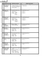
PG-A20X

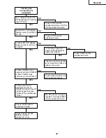
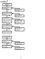
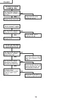
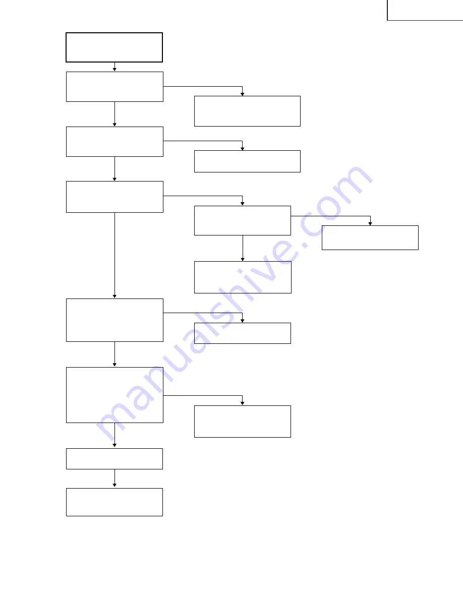
YES

YES

YES

YES

YES

NO

Checking the 

microprocessor 

peripherals

Is a voltage of about 3.3V 
DC applied to pins (3) and 
(5) of IC1703?

Check IC1703 and its 
peripheral circuits, or IC1702 
and its peripheral circuits.

Is the lamp access lid 
open? Is the P2006 (LF) 
tight in the socket? 

Check IC2002 and its 
peripheral circuits.

Check IC8202, IC8203, 
IC2601 and their 
peripheral circuits.

Check IC1704 and its 
peripheral circuits.

NO

Is about DC 2.5V applied 
between pins (5) and (8) of 
IC1704?

NO

Check IC8009 and its 
peripheral circuits.

NO

See if the fan is running as 
specified. Or check IC8003 
and its peripheral circuits.

NO

Is about DC 2.5V applied 
between pins (4) and (3) of 
IC8009?

Is there about DC3V 
applied at pin (21) of 
IC2002? Do the D0 thru D7 
signals appear as pulse 
signals on the oscilloscope 
screen?

Fully close the lamp access 
lid. Or insert the P2006 (LF) 
tightly in the socket.

YES

Check IC8010, IC8011 and 
their peripheral circuits.

NO

Is there 133-MHz clock 
output at pin (6) of IC8010? 
Is there 75-MHz clock 
output at pin (6) of IC8011?

Summary of Contents for Notevision PG-A20X

Page 1: ...TOR LCD PROJEKTOR Im lnteresse der Benutzersicherheit erforderliche Sicherheitsregeln in einigen Ländern muß das Gerät in seinen Originalzustand gebracht werden Außerdem dürfen für die spezifizierten Bauteile nur identische Teile verwendet werden SERVICE MANUAL SERVICE ANLEITUNG SHARP CORPORATION This document has been published to be used for after sales service only The contents are subject to c...

Page 2: ...ABINET AND MECHANICAL PARTS 118 Ë ACCESSORIES PARTS 122 Ë PACKING PARTS 122 PACKING OF THE SET 123 INHALT TECHNISCHE DATEN 38 HINWEISE FÜR DAS WARTUNGSPERSONAL 39 BEDIENUNGSANLEITUNG 41 ABMESSUNGEN 47 ENTFERNEN DER HAUPTTEILE 48 RÜCKSTELLEN DES LAMPENBETRIEBSZEIT TIMERS 52 BESCHREIBUNG DER OPTIK EINHEIT 53 ELEKTRISCHE EINSTELLUNG 55 FEHLERSUCHTABELLE 63 CHASSIS ANORDNUNG 70 BLOCKSCHALTBILD 72 Seit...

Page 3: ...d for Europe except U K 6 1 8 m Power cord for U K Hong Kong and Singapore 6 1 8 m Power cord for Australia New Zealand and Oceania 6 1 8 m RGB cable 9 10 3 0 m Carrying case Lens cap attached Extra air filter Projector manual and technical reference CD ROM QUICK GUIDE label Operation manual Lamp unit Lamp cage module BQC PGA20X 1 Remote control RRMCGA187WJSA Two R 6 batteries AA size UM SUM 3 HP ...

Page 4: ...4567890123456789012345678901212 12345678901234567890123456789012123456789012345678901234567890121234567890123456789012345678901212 SAFETY NOTICE Many electrical and mechanical parts in LCD Projector have special safety related characteristics These characteristics are often not evident from visual inspection nor can protection afforded by them be necessarily increased by using replacement componen...

Page 5: ... avec soin NOTE TO SERVICE PERSONNEL UV RADIATION PRECAUTION The light source UHP lamp in the LCD projector emits small amounts of UV Radiation AVOID DIRECT EYE AND SKIN EXPOSURE To ensure safety please adhere to the following 1 Be sure to wear sun glasses when servicing the projector with the lamp turned on and the top enclosure removed 2 Do not operate the lamp outside of the lamp housing 3 Do n...

Page 6: ...high temperature during units operation replacement of the lamp should be done at least one hour after the power has been turned off to allow the lamp to cool off Installing the new lamp make sure not to touch the lamp bulb replace the lamp by holding its reflector 2 Use original replacement only DANGER Ne jamais mettre sous tension sans la lampe pour éviter un choc électrique ou des dommages des ...

Page 7: ... L éclair terminé d une flèche à l intérieur d un triangle indique à l utilisateur que les pi eces se trouvant dans l appareil sont susceptibles de provoquer une décharge électrique Le point d exclamation à l intérieur d un triangle indique à l utilisateur que les instructions de fonctionnement et d entretien sont détaillées dans les documents fournis avec le projecteur RISQUE D ÉLECTROCUTION NE P...

Page 8: ... higher than the conventional lead solder by 40 C and as it has poor solder wettability you may be apt to keep the soldering bit in contact with the PWB for extended period of time However since the land may be peeled off or the maximum heat resistance temperature of parts may be exceeded remove the bit from the PWB as soon as you confirm the steady soldering condition Lead free solder contains mo...

Page 9: ...stone Correction mode AUTO SYNC button For automatically adjusting images when connected to a computer Volume buttons For adjusting the speaker sound level or the Keystone Correction Zoom knob Focus ring Speaker Foot release Front adjustment foot Front adjustment foot Air filter cooling fan Intake vent on the bottom of the projector Exhaust vent Foot release on the side of the projector Projector ...

Page 10: ...terminal Shared audio input terminal for INPUT 1 2 and 3 INPUT 2 terminal Terminal for connecting video equipment with an S video terminal INPUT 3 terminal Terminal for connecting video equipment Projector Rear View Using the Kensington Lock This projector has a Kensington Security Stan dard connector for use with a Kensington MicroSaver Security System Refer to the information that came with the ...

Page 11: ... Page Down and Page Up keys on a computer keyboard when using the optional Remote Receiver AN MR1EL ENLARGE Enlarge Reduce buttons For enlarging or reducing part of the image AUTO SYNC button For automatically adjusting images when connected to a computer Volume buttons For adjusting the speaker sound level INPUT buttons For switching to the respective input modes FREEZE button For freezing images...

Page 12: ... control once they have run out as leaving them in can cause them to leak Battery fluid from leaked batteries is harmful to skin therefore be sure to first wipe them and then remove them using a cloth The batteries included with this projector may run down in a short period depending on how they are kept Be sure to replace them as soon as possible with new batteries Remove the batteries from the r...

Page 13: ...TER RETURN BUTTONS REMOTE CONTROL KEY PC control A computer can be used to control the projector by connecting an RS 232C serial control cable cross type sold separately to the projector See page 20 for connection Communication conditions Set the serial port settings of the computer to match that of the table Signal format Conforms to RS 232C standard Parity bit None Baud rate 9 600 bps Stop bit 1...

Page 14: ...ted Note Pin 8 CS and Pin 7 RS are short circuited inside the projector RS 232C Cable recommended connection 9 pin D sub female connector Pin No Signal Pin No Signal 1 CD 1 CD 2 RD 2 RD 3 SD 3 SD 4 ER 4 ER 5 SG 5 SG 6 DR 6 DR 7 RS 7 RS 8 CS 8 CS 9 C I 9 CI Note Depending on the controlling device used it may be necessary to connect Pin 4 and Pin 6 on the controlling device e g PC INPUT 1 RGB Signa...

Page 15: ...p View Rear View Front View Bottom View ø 66 4 10 13 64 258 8 3 9 64 79 5 11 45 64 297 1 35 64 39 2 3 13 64 81 3 33 64 89 7 7 64 180 5 9 1 32 229 49 64 19 1 7 11 16 195 5 55 64 148 5 13 64 5 6 21 32 169 7 3 32 180 25 32 19 5 7 53 64 198 5 M4 M4 M4 1 59 64 48 5 ...

Page 16: ... bottom of the set 2 3 Remove the two hooks and detach the top body 2 1 2 3 2 3 2 2 Top Body REMOVING OF MAJOR PARTS 1 Removing the lamp unit 1 1 Loosen a screw and detach the lamp door 1 2 Loosen the two screws Hold the lamp unit by the handle and pull it in the direction of allow 1 1 Lamp Door Lamp Unit 1 2 1 2 ...

Page 17: ...the exhaust cover optical mechanism unit R C receiver PWB and speaker 4 1 Remove the two screws and detach the lamp socket 4 2 Detach the Power Ballast holder cover 4 3 Remove all the connectors from optical mechanism unit 4 4 Remove the nine screws and take out of the optical mechanism unit and the exhaust cover 4 5 Detach the R C receiver PWB 4 6 Detach the Speaker Power Ballast Holder Cover Exh...

Page 18: ...wo screws and cooling fan AC Inlet Ballast Unit Power PWB Cooling Fan Bottom Shield Shield Cover 5 7 5 2 5 6 5 5 5 4 5 5 5 3 5 3 5 5 5 1 Note When mounting the shield bottom for power supply ballast PSLDMA189WJFW on the power ballast holder ass y CHLDZA135WJ01 make sure that it is inserted into the following place Be sure to insert the claw of the bottom shield into the gap between the upper shiel...

Page 19: ... screw and detach the leaf switch 6 3 Remove a screw and two hooks Detach the spacer B Take out of the fan LCD R G intake duct B assembly 6 4 Remove a screw and detach the fan LCD R G 6 5 Remove the two screws and detach the fan LCD B 6 1 6 2 6 3 6 5 6 4 6 3 6 3 Intake Duct B Fan LCD R G Leaf Switch Fan LCD B 6 5 6 3 Spacer B ...

Page 20: ...ecurely install the cover If the power indicator blinks even when the filter lamp unit cover is securely installed contact your nearest Sharp Authorized Projec tor Dealer or Service Center for advice Green on Red on Red blinks Green on Green blinks when the lamp is warming up or shutting down 1 2 3 Tab This projector is equipped with air fil ters to ensure the optimal operating condition of the pr...

Page 21: ...G r e f l e c t o r Fly eye lens Input Fly eye lens Output Relay lens 1 M i r r o r R 1 Relay lens 2 R dichroic filter M i r r o r R 2 Relay lens 3 Input polariser R LCD R LCD B LCD G Output pre polariser G Input polariser B Input polariser G Condensing lens B Projection lens Blue Green Red Red PBS Green Output pre polariser B Output pre polariser R C r o s s d i c h r o i c p r i s m Condensing l...

Page 22: ...ction lens assembly from each other 3 Replace the prism holder unit with new one Take the above steps 1 and 2 in reverse order Note Even if just one of the LCD panels is defective it is necessary to replace the entire prism holder unit Do not replace just the defective LCD panel only 1Prism holder unit lock screws 2Projection lens lock screws Projection lens assembly Prism holder unit R LCD panel ...

Page 23: ... R G B Contrast adjustment 1 Select the following group and subjects Group AD Subject R Contrast G Contrast B Contrast Process GAMMA interlock 2 Feed the SVGA white sig nal with an amplitude level of 96 0 67 Vp p 1 Watching the screen adjust the R G and B Con trast settings so that because of some pixel drop outs the bright color zone should become just about a half 3 DTV Brightness Contrast adjus...

Page 24: ...P1301 Adjust with PSIG L Adjust with PSIG H 7 R G B Black Level Signal Amplitude adjustment 1 Select the following group and subjects Group OUTPUT1 Subject On Green adjustment G1 BLK G1 GAIN On Red Adjustment R1 BLK R1 GAIN On Blue Adjustment B1 BLK B1 GAIN 2 Make sure the process ad justment color bags appear onscreen 3 Connect a oscilloscope to pin 2 of P1301 for the G setting 4 Connect the osci...

Page 25: ...nt 1 Feed the RGB 50 gray signal SVGA 2 Select the following group and subjects Group OUTPUT1 Subject S R1 BLK S B1 BLK 1 Adjust the R1 BLK and B1 BLK B settings so that the chromaticity based on CL200 becomes as follows 6500K x 313 5 y 334 5 12 Video white balance adjustment 14 DTV white balance adjustment 9 Chiral phase selection of LCD panel 1 Group OUTPUT3 Subject OPT MECH 1 Adjust the GR and ...

Page 26: ...ing group and subject Group DTV Subject Tint 1 Check the fixed value Tint 5 16 Video Tint adjustment 1 Select the following group and subject Group VIDEO Subject N Tint P Tint S Tint 1 Check the fixed value N Tint 5 P Tint 5 S Tint 5 15 Automatic color irregularity correction 1 Apply the automatic color correction using the auto matic color irregularity cor rection system 1 Make sure that no remar...

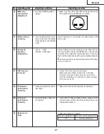
Page 27: ...s and V Pos settings can be au tomatically adjusted 29 Auto sync performance checking No Adjusting point Adjusting conditions Adjusting procedure 26 Automatic keystone initialization Group LINE Subject Calibration Select Calibration in the process mode Place the set on a level surface Press the ENTER key on the remote controller The calibration setting becomes 1 first and then both the calibration...

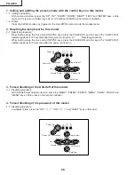
Page 28: ...000H indicator appears for 60 seconds after the power is turned on 2 1 Resetting procedure While holding down the Vol and AUTOSYNC keys press the POWER ON and Vol keys The LAMP 000H indicator appears for 60 seconds after the power is turned on 3 Forced disabling of the Anti Seft of this model 3 1 Disabling procedure With Anti Seft input window onscreen press the MENU ENTER ENTER MENU UNDO UNDO and...

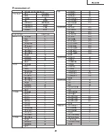
Page 29: ... S Color 5 Sharpness 3 CTI Level 1 LTI Level 0 CB Offset 7 VIDEO CR Offset 7 Bright 13 B DRIVE 41 R DRIVE 41 EXIT AD R Bright 63 G Bright 63 B Bright 63 R Contrast 172 G Contrast 172 B Contrast 172 EXIT OUTPUT1 R1 BLK 200 R1 GAIN 166 G1 BLK 200 G1 GAIN 166 B1 BLK 200 B1 GAIN 166 S R1 BLK 200 S R1 GAIN 166 S G1 BLK 200 S G1 GAIN 166 S B1 BLK 200 S B1 GAIN 166 EXIT OUTPUT2 PSIG H 90 PSIG L 16 VCENTE...

Page 30: ...2 SS3 EU SS4 US SS5 JPN SS6 CHIN EXIT TEMP Temp1 Parameter of sensor 1 Temp2 Parameter of sensor 2 Temp3 No Use Temp4 No Use EXIT PATTERN Cross Hatch Color Bar EXIT LAMP Current Time Current time of use History1 One earlier History2 Two earlier History3 Three earlie History4 Four earlier TOTAL TIME Total operating hours EXIT LINE OFF LED CHECK Calibration 0 K Sensor EXIT ...

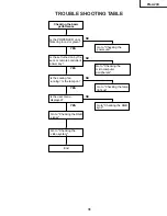
Page 31: ...g the power unit Go to Checking the lamp light up NO Is the set turned on by the set s or remote controller s power key Go to Checking the microcomputer peripherals NO Go to Checking the RGB sync Go to Checking the RGB signal Go to Checking the video system End NO Is the cooling fan running Is the lamp on Is the user menu displayed YES YES ...

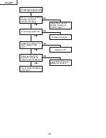
Page 32: ...y Insert the connectors CN701 CN702 and CN751 tightly Replace the bimetal NO Replace F701 NO Check Q702 for damage Replace as required NO Is the bimetal switch off Is there AC voltage 110 240V applied across C701 Disconnect the CN751 connector Is there 6V output at pins 3 and 4 Check the MAIN PWB for short circuit ...

Page 33: ...circuits NO Is about DC 2 5V applied between pins 5 and 8 of IC1704 NO Check IC8009 and its peripheral circuits NO See if the fan is running as specified Or check IC8003 and its peripheral circuits NO Is about DC 2 5V applied between pins 4 and 3 of IC8009 Is there about DC3V applied at pin 21 of IC2002 Do the D0 thru D7 signals appear as pulse signals on the oscilloscope screen Fully close the la...

Page 34: ... lamp socket disconnected Reconnect the lamp socket tightly Are the CN751 and CN752 harnesses tight in position in the power unit and ballast unit as well Are these harnesses free of damage Are there 3V High level and 1V applied at pins 1 and 13 respectively of CN751 in the power unit NO Checking the RGB sync Check IC6001 and its peripheral circuits NO YES Are there signal inputted into pins 30 31...

Page 35: ... and IC1301 Check IC2601 and its peripheral circuits NO Are there input signals at pins 2 and 31 of SC1101 SC1201 and SC1301 Check IC1103 and its peripheral circuits Are there input signals at pins 3 of SC1101 and SC1301 and pin 30 of SC1201 Check IC1101 IC1201 IC1301 and their peripheral circuits NO Check the connection of LCD panels And when video signal and OSD are also not disaplayed replace t...

Page 36: ...06 and its peripheral circuits YES NO Checking IC3102 RGB signal output circuit Are there signal outputs at pins 66 R Y 68 B Y 69 Y of IC3102 Go to No colour or unusual tone No Y signal or Out of sync YES NO Are there RGB outputs waveforms at pins 35 37 and 39 of IC3102 Check the data transfer and other performance at pins 55 and 56 of IC3102 NO Are there output waveforms at the emitters of Q3110 ...

Page 37: ...e video system Is the specified voltage EA connectors Check power circuit and its peripheral parts Is the lamp on Go to Lamp light up YES Is the video signal inputted into the pin 7 of IC3506 Check the video terminal and its peripheral circuits YES Check IC3105 and its peripheral circuits Check IC1103 and its peripheral circuits Is the signal inputted into the pins 39 and 41 of IC3105 Check Q3501 ...

Page 38: ...ritannien 6 1 8 m Netzkabel für Großbritannien Hongkong und Singapur 6 1 8 m Netzkabel für Australien Neuseeland und Ozeanien 6 1 8 m RGB Kabel 9 10 3 0 m Tragetasche Objektivkappe befestigt zusätzlicher Luftfilter Projektorhandbuch und technische Referenz CD ROM QUICK GUIDE Schnellanleitung Aufkleber Bedienungsanleitung Lampeneinheit Lampen Gehäusemodul BQC PGA20X 1 Fernbedienung RRMCGA187WJSA zw...

Page 39: ...F AUGEN UND HAUT MUSS VERMIEDEN WERDEN Zur Gewährleistung der Sicherheit muß folgendes beachtet werden 1 Bei Arbeiten am Projektor bei eingeschalteter Lampe und abgenommenem oberen Gehäuse muß unbedingt eine Sonnenbrille getragen werden 2 Die Lampe darf nicht außerhalb des Lampengehäuses eingeschaltet werden 3 Betrieb für länger als 2 Stunden bei abgenommenem Gehäuse ist nicht zulässig Zur Beachtu...

Page 40: ... der von bleihaltigem Lötzinn ist und außerdem schlechte Löt Benetzbarkeit aufweist kann es erforderlich werden die Lötspitze längere Zeit in Kontakt mit der Platine zu halten Da die Lötlauge abfliessen kann oder der maximale Hitzewiderstand von Teilen überschritten werden kann die Lötspitze sofort von der Platine nehmen sobald eine gute Lötung erzielt ist Bleifreier Lötzinn enth_lt mehr Zinn und ...

Page 41: ...t Lautstärke Tasten Für das Einstellen des Lautsprecher Tonpegels oder der Trapezverzerrungskorrektur Zoom Knopf Fokusring Lautsprecher Fuß Entriegelung Vorderer Einstellfuß Vorderer Einstellfuß Luftfilter Ventilator Luftzufuhr auf der Unterseite des Projektors Luftaustrittöffnung Fuß Entriegelung an der Projektorseite Anbringen und Abnehmen der Objektivkappe Drücken Sie an den beiden Tasten der O...

Page 42: ...ss Geteilter Audioeingabeanschluss für INPUT 1 2 und 3 INPUT 2 Anschluss Anschluss für ein Videogerät mit einem S VIDEO Anschluss INPUT 3 Anschluss Anschluss für ein Videogerät Projektor Hintersicht Verwendung der Kensington Sperre Dieser Projektor ist mit einem K e n s i n g t o n S i c h e r heitsstandardanschluss für die Verwendung des Kensington MicroSaver Sicherheits systems ausgestattet Lese...

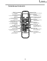
Page 43: ...rnbedienungsempfänger AN MR1EL verwendet wird ENLARGE Tasten Vergrößern Verkleinern Für das Vergrößern oder Verkleinern eines Bildteils AUTO SYNC Taste Für das automatische Einstellen von Bildern wenn ein Computer angeschlossen ist Lautstärke Tasten Für das Einstellen des Lautsprecher Tonpegels INPUT Tasten Für das Umschalten auf die entsprechenden Eingabemodi FREEZE Taste Für das Einfrieren von B...

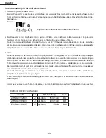
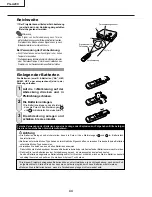
Page 44: ...he Verwendung der Batterien kann eine Leckage oder Explosion zur Folge haben Bitte befolgen Sie die unten stehenden Vorsichtsmaßnahmen Achtung Die Batterien einlegen und sicherstellen dass die Pole mit den Markierungen und im Batteriefach übereinstimmen Batterien unterschiedlichen Typs haben unterschiedliche Eigenschaften verwenden Sie deshalb keine Batterien unterschiedlichen Typs zusammen Verwen...

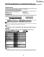
Page 45: ...einen Wert innerhalb der in Klammern unter STEUERUNGSINHALTE angegebenen Spanne ein PC Steuerung Der Projektor kann durch einen Anschluss an einen Computer über ein serielles RS 232C Steuerkabel Kreuztyp separat erhältlich über den Computer gesteuert werden Siehe Seite 20 Anschlussanleitungen Kommunikationsbedingungen Legen Sie die seriellen Porteinstellungen des Computers so fest dass sie denen d...

Page 46: ...rn des Projektors kurzgeschlossen RS 232C Kabel empfohlene Verbindung 9 Pin D Sub weiblich Pin Nr Signal Pin Nr Signal 1 CD 1 CD 2 RD 2 RD 3 SD 3 SD 4 ER 4 ER 5 SG 5 SG 6 DR 6 DR 7 RS 7 RS 8 CS 8 CS 9 CI 9 CI Hinweis Je nach verwendetem Steuergerät ist es unter Umständen erforderlich Pin 4 und Pin 6 am Steuergerät z B am PC anzuschließen INPUT 1 RGB Signalanschluss 15 Pin Mini D Sub weiblich RGB E...

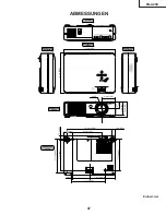
Page 47: ...r Seite Ansicht von der Seite Ansicht von vorne Ansicht von unten ø 66 4 10 13 64 258 8 3 9 64 79 5 11 45 64 297 1 35 64 39 2 3 13 64 81 3 33 64 89 9 1 32 229 7 7 64 180 5 49 64 19 1 7 11 16 195 5 55 64 148 5 13 64 5 6 21 32 169 7 3 32 180 25 32 19 5 7 53 64 198 5 M4 M4 M4 1 59 64 48 5 ...

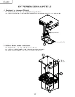
Page 48: ...ts entfernen 2 3 Die beiden Haken lösen dann das obere Gehäuse abnehmen 2 1 2 3 2 3 2 2 Oberes Gehäuse ENTFERNEN DER HAUPTTEILE 1 Ausbau der Lampen Einheit 1 1 Die Schraube lösen dann die Lampenabdeckung abnehmen 1 2 Die beiden Schrauben lösen Die Lampen Einheit am Griff anfassen dann in Pfeilrichtung ziehen 1 1 1 2 1 2 Lampen Einheit Lampenabdeckung ...

Page 49: ... R C Receiver Leiterplatte und des Lautsprechers 4 1 Die beiden Schrauben entfernen dann den Lampensockel abnehmen 4 2 Die Abdeckung für den Netzgerät Vorschaltwiderstands Halter abnehmen 4 3 Alle Stecker von der Optikmechanismus Einheit und der Auslaßabdeckung abziehen 4 4 Die neun Schrauben entfernen dann die Optikmechanismus Einheit herausnehmen 4 5 Die R C Receiver Leiterplatte abnehmen 4 6 De...

Page 50: ...en 5 7 Die beiden Schrauben entfernen d a n n d a s K ü h l g e b l ä s e herausnehmen Hinweis Wenn die Abschirmung unten der Netzgerät Vorschaltwiderstands Einheit PSLDMA189WJFW an der Halter Baugruppe des Netzgerät Vorschaltwiderstands CHLDZA 135WJ01 montiert wird muß sichergestellt werden daß diese wie unten beschrieben angebracht wird Unbedingt die Klaue der unteren Abschirmung in den Spalt zw...

Page 51: ... beiden Haken entfernen Das Abstandsstück B abnehmen Die Baugruppe Kühlgebläse LCD R G und die Einlaßluftführungs Einheit B herausnehmen 6 4 Die Schraube entfernen dann die Baugruppe Kühlgebläse LCD R G ausbauen 6 5 Die beiden Schrauben entfernen dann die Kühlgebläse LCD B herausnehmen 6 1 6 2 6 3 6 5 6 4 6 3 6 3 6 5 6 3 Kühlgebläse LCD B Abstandsstück B Kühlgebläse LCD R G Einlaßluftführung B Bla...

Page 52: ...aufsatz entfernen 6 Den Luftfilter wieder einsetzen Den Luftfilter unter den Laschen auf der Abdeckung der Filter Lampeneinheit platzieren 7 Die Abdeckung der Filter Lampeneinheit wieder einsetzen Die Lasche auf der Abdeckung der Filter Lampeneinheit 1 ausrichten und so platzieren während auf die Lasche 2 gedrückt wird um sie zu schließen Anschließend die Benutzer Wartungsschraube 3 anziehen um di...

Page 53: ...Ausgangs Vorpolarisator B Ausgabe polarisator R LCD B Zweifarbiges Kreuzprisma Spiegel R2 R Kaltlichtfilter Relaislinse 2 S p i e g e l R 1 Relaislinse 1 Rot LCD G Ausgangs Vorpolarisator G Sammellinse B S p i e g e l B Sammellinse G Grün Eingabe polarisator G Grün Rot G Reflektor UV Reflektor Blau B Reflektor Sammellinse S p i e g e l R G B Fliegenaugenoptik Ausgang Fliegenaugenoptik Eingang PBS ...

Page 54: ...Einheit trennen 3 Die Prismenhalter Einheit durch ein Neuteil ersetzen Die obigen Schritte 1 und 2 in umgekehrter Reihenfolge ausführen Hinweis Selbst wenn auch nur eine der LCD Tafeln defekt ist muß die Prismenhalter Einheit ersetzt werden Auf keinen Fall nur die defekte LCD Tafel auswechseln 1 2 Optik Einheit G LCD Tafel Halteschrauben der Prismenhalter Einheit R LCD Tafel Prismenhalter Einheit ...

Page 55: ...Einstellverfahren 2 2 Einstellung des R G B Kontrastes 1 Die folgenden Gruppen und Positionen wählen Gruppe AD Position R Contrast G Contrast B Contrast GAMMA Synchronisationsablauf 2 Ein SVGA Weißsignal mit einem Amplitudenpegel von 96 0 67 Vp p zuführen 1 Den Bildschirm beobachten und die R G und B Kontrastwerte so einstellen daß wegen eines geringen Bildpunkteschwunds sich die helle Farbzone au...

Page 56: ...ignalamplitude 1 Die folgenden Gruppen und Positionen wählen Gruppe OUTPUT1 Position Für Grün Einstellung G1 BLK G1 GAIN Für Rot Einstellung R1 BLK R1 GAIN Für Blau Einstellung B1 BLK B1 GAIN 2 Sich vergewissern daß die Farbmarkierungen für die Prozeßeinstellung am Bildschirm angezeigt werden 3 Für die G Einstellung ein Synchroskop mit P1301 2P verbinden 4 F ü r d i e R u n d B E i n s t e l l u n...

Page 57: ...Ein RGB Grausignal mit 50 zuführen SVGA 2 Die folgenden Gruppen und Positionen wählen Gruppe OUTPUT1 Position S R1 BLK S B1 BLK 1 Die Einstellungen für S R1 BLK und B1 BLK so vornehmen daß ein Farbwert von x 313 5 bzw y 334 5 erhalten wird 6500K 12 Video Weißbalance Einstellung 14 DTV Weißbalance Einstellung 9 Optisch aktive Phasenwahl des LCDs 1 Gruppe OUTPUT3 Gegenstand OPT MECH 1 Die GR und GL ...

Page 58: ...ton einstellung 1 Die folgenden Gruppen und Positionen wählen Gruppe DTV Position Tint 1 Den Festwert überprüfen Tint 5 18 Einstellung der Bildschärfe 1 Gruppe VIDEO Gegenstand Schärfe 1 Den Standardwert überprüfen Schärfe 3 16 Videofarbton Einstellung 1 Die folgenden Gruppen und Positionen wählen Gruppe VIDEO Position N Tint P Tint S Tint 1 Den Festwert überprüfen N Tint 5 P Tint 5 S Tint 5 15 Au...

Page 59: ... den Clock Phase H POS und V POS automatisch eingestellt werden können 29 Überprüfung der Auto Sync Leistungswerte 24 Einstellung der RGB Farbton wiedergabe 1 Sich vergewissern daß die 100 und 95 Abstufungen für Weiß sowie die 0 und 5 Abstufungen für Schwarz sichtbar sind 1 Das SMPTE Testbildsignal zuführen 26 Automatische Trapezentzerrung Gruppe LINE Gegenstand Kalibrierung Im Prozeßmodus Kalibri...

Page 60: ...MP 000H erscheint nun für 60 Sekunden nachdem die Stromversorgung eingeschaltet wurde 3 Erzwungenes Deaktivieren der Diebstahlschutz Funktion an diesem Modell 3 1 Vorgehensweise beim Deaktivieren Während das Diebstahlschutz Eingabemenü am Bildschirm angezeigt wird an der Fernbedienungseinheit in der angegebenen Reihenfolge die Tasten MENU ENTER ENTER MENU UNDO UNDO und MENU drücken 4 Erzwungenes D...

Page 61: ... 5 S Color 5 Sharpness 3 CTI Level 1 LTI Level 0 CB Offset 7 VIDEO CR Offset 7 Bright 13 B DRIVE 41 R DRIVE 41 EXIT AD R Bright 63 G Bright 63 B Bright 63 R Contrast 172 G Contrast 172 B Contrast 172 EXIT OUTPUT1 R1 BLK 200 R1 GAIN 166 G1 BLK 200 G1 GAIN 166 B1 BLK 200 B1 GAIN 166 S R1 BLK 200 S R1 GAIN 166 S G1 BLK 200 S G1 GAIN 166 S B1 BLK 200 S B1 GAIN 166 EXIT OUTPUT2 PSIG H 90 PSIG L 16 VCEN...

Page 62: ...ür Sensor 1 Temp2 Parameter für Sensor 2 Temp3 Nicht belegt Temp4 Nicht belegt EXIT PATTERN Cross Hatch Color Bar EXIT LAMP Current Time Gegenwärtige Verwendungszeit History1 Vorheriger Zyklus History2 Zwei Zyklen vorher History3 Drei Zyklen vorher History4 Vier Zyklen vorher TOTAL TIME Gesamtbetriebs stunden EXIT LINE OFF LED CHECK Calibration Zeilen Neigungswinkel K Sensor 0 3 oder 129 131 wenn ...

Page 63: ...IN Kann das Gerät mit der Einschalttaste oder über die Fernbedienungseinheit eingeschaltet werden Mit dem Abschnitt Überprüfung der Mikrocomputer Peripherieschaltkreise fortfahren NEIN Mit dem Abschnitt Überprüfen der RGB Synchronisierung fortfahren Mit dem Abschnitt Überprüfen des RGB Signals fortfahren Mit dem Abschnitt Überprüfen des Video Systems fortfahren Ende NEIN Läuft das Kühlgebläse Ist ...

Page 64: ...esteckt Den Bimetall Schalter ersetzen NEIN F701 ersetzen NEIN Q702 auf Beschädigung überprüfen und nötigenfalls ersetzen NEIN Ist der Bimetall Schalter ausgeschaltet Liegt eine Wechselspannung 110 240 V an C701 an Den Stecker CN751 abziehen Liegt eine Ausgangsspannung von 6 V an den Stiften 3 und 4 an Die Hauptleiterplatte MAIN PWB auf Kurzschluß überprüfen ...

Page 65: ... ca 2 5 V zwischen den Stiften 5 und 8 von IC1704 an NEIN IC8009 und seine Peripherie Schaltkreise überprüfen NEIN Überprüfen ob das Kühlgebläse entsprechend der Spezifikation funktioniert bzw IC8003 und seine Peripherie Schaltkreise überprüfen NEIN Liegt eine Gleichspannung von ca 2 5 V zwischen den Stiften 4 und 3 von IC8009 an Liegt eine Gleichspannung von ca 3 V an Stiften 21 von IC2002 an Ers...

Page 66: ...st die Lampenfassung locker Die Lampenfassung fest anschließen Sind die Zuleitungskabel für CN751 und CN752 fest am Netzteil bzw an der Vorschaltwiderstands Einheit angeschlossen Befinden sich die Kabel in einwandfreiem Zustand Liegt eine Spannung von 3 V Hochpegel bzw 1 V an den Stiften 1 und 13 von CN751 im Netzteil an NEIN Überprüfen der RGB Synchronisierung IC6001 und seine Peripherie Schaltkr...

Page 67: ...e Peripherie Schaltkreise überprüfen NEIN Liegt am Stift 31 von SC1101 SC1201 und SC1301 ein Signal an IC1103 und seine Peripherie Schaltkreise überprüfen Liegen ihre Signale am Stift 3 von SC1101 und SC1301 sowie am Stift 30 von SC1201 an IC1101 IC1201 IC1301 und ihre Peripherie Schaltkreise überprüfen NEIN Die LCD Anzeige auf korrekten Anschluß überprüfen Wenn weder Videosignal noch OSD angezeig...

Page 68: ...eise überprüfen JA NEIN Überprüfen von IC3102 RGB Ausgangssignal Schaltkreis Liegen Ausgangssignale an den Stiften 66 R Y 68 B Y und 69 Y von IC3102 an Mit dem Abschnitt Keine Farbe oder abweichender Farbton Kein Y Signal oder Außerhalb der Synchronisierung fortfahren JA NEIN Liegen RGB Ausgangswellenformen an den Stiften 35 37 und 39 von IC3102 an Den Datentransfer und andere Leistungsparameter a...

Page 69: ... Überprüfen des Video Systems Liegt die spezifizierte Spannung an den EA Steckern an Den Leistungsschaltkreis und seine Komponenten überprüfen Leuchtet die Lampe auf Mit dem Abschnitt Überprüfung der Lampenfunktion fortfahren JA Liegt am Stift 7 von IC3506 ein Videosignal an Die Video Anschlüsse und ihre Peripherie Schaltkreise überprüfen JA IC3105 und seine Peripherie Schaltkreise überprüfen IC11...

Page 70: ...8 7 10 9 6 5 4 3 2 1 A B C D E F G H 70 PG A20X CHASSIS LAYOUT CHASSIS ANORDNUNG ...

Page 71: ...17 16 19 18 15 14 13 12 11 10 71 PG A20X ...

Page 72: ...8 7 10 9 6 5 4 3 2 1 A B C D E F G H 72 PG A20X BLOCK DIAGRAM BLOCKSCHALTBILD ...

Page 73: ...17 16 19 18 15 14 13 12 11 10 73 PG A20X ...

Page 74: ...8 7 10 9 6 5 4 3 2 1 A B C D E F G H 74 PG A20X OVERALL WIRING DIAGRAM GESAMTSCHALTPLAN ...

Page 75: ...17 16 19 18 15 14 13 12 11 10 75 PG A20X ...

Page 76: ...NS SPANNUNGSMESSUNGEN 1 Spannungen an den Prüfpunkten werden bei einer Netzspannung von 220V gemessen Signale werden für die Wartung mit einem Farbbalken Signal generator zugeführt und Spannungen werden mit einem Meßinstrument 20 k V er mittelt SIGNALFORMMESSUNGEN 1 Die Wellenformen an den Testpunkten werden bei einer Netzspannung von 220V verfolgt Signale werden für die Wartung mit einem Farbbalk...

Page 77: ... 2 GTP P1301 2 H F5µsec div V 2V div 3 BTP P1301 3 H 5µsec div V 2V div 4 P SIG TP1101 H 10µsec div V 2V div 5 VST IC2604 12 H 10µsec div V 1V div 6 HST10 IC2604 17 H 5µsec div V 1V div 7 Y IC3506 25 H 20µsec div V 0 2V div 8 C IC3506 27 H 20µsec div V 0 2V div 9 Video J402 2 H 20µsec div V 0 2V div ...

Page 78: ...8 7 10 9 6 5 4 3 2 1 A B C D E F G H 78 PG A20X Ë MAIN UNIT HAUPTEINHEIT 1 12 ...

Page 79: ...17 16 19 18 15 14 13 12 11 10 79 PG A20X ...

Page 80: ...8 7 10 9 6 5 4 3 2 1 A B C D E F G H 80 PG A20X Ë MAIN UNIT HAUPTEINHEIT 2 12 ...

Page 81: ...17 16 19 18 15 14 13 12 11 10 81 PG A20X ...

Page 82: ...8 7 10 9 6 5 4 3 2 1 A B C D E F G H 82 PG A20X Ë MAIN UNIT HAUPTEINHEIT 3 12 ...

Page 83: ...17 16 19 18 15 14 13 12 11 10 83 PG A20X ...

Page 84: ...8 7 10 9 6 5 4 3 2 1 A B C D E F G H 84 PG A20X Ë MAIN UNIT HAUPTEINHEIT 4 12 ...

Page 85: ...17 16 19 18 15 14 13 12 11 10 85 PG A20X ...

Page 86: ...8 7 10 9 6 5 4 3 2 1 A B C D E F G H 86 PG A20X Ë MAIN UNIT HAUPTEINHEIT 5 12 ...

Page 87: ...17 16 19 18 15 14 13 12 11 10 87 PG A20X ...

Page 88: ...8 7 10 9 6 5 4 3 2 1 A B C D E F G H 88 PG A20X Ë MAIN UNIT HAUPTEINHEIT 6 12 ...

Page 89: ...17 16 19 18 15 14 13 12 11 10 89 PG A20X ...

Page 90: ...8 7 10 9 6 5 4 3 2 1 A B C D E F G H 90 PG A20X Ë MAIN UNIT HAUPTEINHEIT 7 12 ...

Page 91: ...17 16 19 18 15 14 13 12 11 10 91 PG A20X ...

Page 92: ...8 7 10 9 6 5 4 3 2 1 A B C D E F G H 92 PG A20X Ë MAIN UNIT HAUPTEINHEIT 8 12 ...

Page 93: ...17 16 19 18 15 14 13 12 11 10 93 PG A20X ...

Page 94: ...8 7 10 9 6 5 4 3 2 1 A B C D E F G H 94 PG A20X Ë MAIN UNIT HAUPTEINHEIT 9 12 ...

Page 95: ...17 16 19 18 15 14 13 12 11 10 95 PG A20X ...

Page 96: ...8 7 10 9 6 5 4 3 2 1 A B C D E F G H 96 PG A20X Ë MAIN UNIT HAUPTEINHEIT 10 12 ...

Page 97: ...17 16 19 18 15 14 13 12 11 10 97 PG A20X ...

Page 98: ...8 7 10 9 6 5 4 3 2 1 A B C D E F G H 98 PG A20X Ë MAIN UNIT HAUPTEINHEIT 11 12 ...

Page 99: ...17 16 19 18 15 14 13 12 11 10 99 PG A20X ...

Page 100: ...8 7 10 9 6 5 4 3 2 1 A B C D E F G H 100 PG A20X Ë MAIN UNIT HAUPTEINHEIT 12 12 ...

Page 101: ...17 16 19 18 15 14 13 12 11 10 101 PG A20X ...

Page 102: ...8 7 10 9 6 5 4 3 2 1 A B C D E F G H 102 PG A20X Ë POWER UNIT NETZTEILEINHEIT ...

Page 103: ...17 16 19 18 15 14 13 12 11 10 103 PG A20X ...

Page 104: ...104 6 5 4 3 2 1 A B C D E F G H PG A20X Ë R C RECEIVER UNIT FERNBEDIENUNGSEMPFänGERSEINHEIT ...

Page 105: ...105 6 5 4 3 2 1 A B C D E F G H PG A20X PRINTED WIRING BOARD ASSEMBLIES LEITERPLATTENEINHEITEN Power Unit Wiring Side Netzteinheit Leiterbahnseite Power Unit Component Side Netzteinheit Bestückungsseite ...

Page 106: ...106 6 5 4 3 2 1 A B C D E F G H PG A20X Main Unit Side A Haupt einheit Seite A R C Receiver Unit Side A Fernbedienungsempfängerseinheit Seite A ...

Page 107: ...107 6 5 4 3 2 1 A B C D E F G H PG A20X Main Unit Side B Haupt einheit Seite B R C ReceiverUnit Side B Fernbedienungsempfängerseinheit Seite B ...

Page 108: ...1 MAIN Unit RDENCA029WJN1 POWER Unit RDENCA046WJZZ J BALLAST Unit BS Unit Replacement Item PARTS LIST PARTS REPLACEMENT Parts marked with å are important for maintaining the safety of the set Be sure to replace these parts with specified ones for main taining the safety and performance of the set HOW TO ORDER REPLACEMENT PARTS To have your order filled promptly and correctly please furnish the fol...

Page 109: ...J SN74AHC2G66HDC AE IC8009 VHiSN1G66DC 1Y J SN74AHC1G66HDC AD IC8010 VHiP2040CTR 1Y J P2040C 08TR AM IC8011 VHiP2042ATR 1Y J P2042A 08TR AM IC8202 RH iXA733WJZZQ J M29W800DT70N6 AN IC8203 VHiBR24L64F 1Y J BR24L64F WE2 AK TRANSISTORS Q1101 VSHN1B04FU 1Y J HN1B04FU AC Q1103 VS2SC3928AR 1Y J 2SC3928AR AB Q1105 VS2SA1530AR 1Y J 2SA1530AR AB Q1201 VSHN1B04FU 1Y J HN1B04FU AC Q1203 VS2SC3928AR 1Y J 2SC3...

Page 110: ... VCKYCY1EF104ZY J 0 1 25V Ceramic AA C1203 RC KZA048WJZZY J 10 25V Ceramic AD C1204 VCKYCY1EF104ZY J 0 1 25V Ceramic AA C1205 VCKYCY1EF104ZY J 0 1 25V Ceramic AA C1207 VCKYCY1EF104ZY J 0 1 25V Ceramic AA C1208 VCKYCY1EF104ZY J 0 1 25V Ceramic AA C1209 VCKYCY1AF105ZY J 1 10V Ceramic AC C1210 RC KZA048WJZZY J 10 25V Ceramic AD C1222 VCKYCY1EF104ZY J 0 1 25V Ceramic AA C1223 RC KZA048WJZZY J 10 25V C...

Page 111: ...EF104ZY J 0 1 25V Ceramic AA C2647 VCKYCY1EF104ZY J 0 1 25V Ceramic AA C2648 VCEAPF1CW106MY J 10 16V Electrolytic AB C3102 VCKYCY1AF105ZY J 1 10V Ceramic AC C3103 VCKYCY1AF105ZY J 1 10V Ceramic AC C3104 VCKYCY1AF105ZY J 1 10V Ceramic AC C3105 VCKYCY1AF105ZY J 1 10V Ceramic AC C3106 VCKYCY1AF105ZY J 1 10V Ceramic AC C3107 VCKYCY1EF104ZY J 0 1 25V Ceramic AA C3108 VCCCCY1HH470JY J 47p 50V Ceramic AA...

Page 112: ...CY1EF104ZY J 0 1 25V Ceramic AA C5508 VCKYCY1EF104ZY J 0 1 25V Ceramic AA C5510 VCKYTV1CB105KY J 1 16V Ceramic AC C5511 VCKYCY1EF104ZY J 0 1 25V Ceramic AA C5512 VCKYCY1EF104ZY J 0 1 25V Ceramic AA C6003 VCKYCY1EF104ZY J 0 1 25V Ceramic AA C6006 VCEAPF0JW226MY J 22 6 3V Electrolytic AB C6007 VCKYCY1EB473KY J 0 047 25V Ceramic AA C6008 VCKYCY1EB473KY J 0 047 25V Ceramic AA C6009 VCKYCY1HB102KY J 10...

Page 113: ... AB R1745 VRS CY1JF102JY J 1k 1 16W Metal Oxide AA R1746 VRS CY1JF104FY J 100k 1 16W Metal Oxide AA R1747 VRS CY1JF682FY J 6 8k 1 16W Metal Oxide AA R1749 VRS CY1JF153FY J 15k 1 16W Metal Oxide AA R1750 VRS CY1JF333FY J 33k 1 16W Metal Oxide AA R1751 VRS CY1JF332FY J 3 3k 1 16W Metal Oxide AA R1752 VRS CY1JF123FY J 12k 1 16W Metal Oxide AA R1753 VRS CY1JF682FY J 6 8k 1 16W Metal Oxide AA R1754 VRS...

Page 114: ...de AA R3136 VRS CY1JF102JY J 1k 1 16W Metal Oxide AA R3138 VRS CY1JF101JY J 100 1 16W Metal Oxide AA R3139 VRS CY1JF102JY J 1k 1 16W Metal Oxide AA R3141 VRS CY1JF222JY J 2 2k 1 16W Metal Oxide AA R3142 VRS CJ1JF103JY J 10k 1 16W Metal Oxide AA R3143 VRS CY1JF681JY J 680 1 16W Metal Oxide AA R3144 VRS CY1JF681JY J 680 1 16W Metal Oxide AA R3145 VRS CY1JF103JY J 10k 1 16W Metal Oxide AA R3146 VRS C...

Page 115: ...AA R8014 VRS CY1JF000JY J 0 1 16W Metal Oxide AA R8016 VRS CY1JF000JY J 0 1 16W Metal Oxide AA R8018 VRS CJ1JF222JY J 2 2k 1 16W Metal Oxide AA R8019 VRS CJ1JF182JY J 1 8k 1 16W Metal Oxide AA R8020 VRS CY1JF101JY J 100 1 16W Metal Oxide AA R8021 VRS CY1JF000JY J 0 1 16W Metal Oxide AA R8023 VRS CJ1JF470JY J 47 1 16W Metal Oxide AA R8024 VRS CY1JF000JY J 0 1 16W Metal Oxide AA R8025 VRS CJ1JF220JY...

Page 116: ...LN 0058CEZZY J Ferrite Bead AB FB4005 RBLN 0058CEZZY J Ferrite Bead AB FB4006 RBLN 0058CEZZY J Ferrite Bead AB FB4007 RBLN 1037CEZZY J Ferrite Bead AB FB4008 RBLN 1037CEZZY J Ferrite Bead AB FB4009 RBLN 1037CEZZY J Ferrite Bead AB FB4010 RBLN 1037CEZZY J Ferrite Bead AB FB5001 RBLN 0061TAZZY J Ferrite Bead AD FB5501 RBLN 0061TAZZY J Ferrite Bead AD FB5502 RBLN 0061TAZZY J Ferrite Bead AD FB6002 RB...

Page 117: ... J 0 47 16V Ceramic AD C718 95C0C195E1030 J 0 01 50V Ceramic AC C720 95C0C1Q0A1060 J 10 6 3V Ceramic AQ C721 95C0C193A4720 J 4700p 50V Ceramic AM C722 95C0C195C1040 J 0 1 25V Ceramic AD C723 95C0C194E1010 J 100p 50V Ceramic AC C724 95C0C1B2S4700 J 47p 2kV Ceramic AE C725 95C0C194E1020 J 1000p 50V Ceramic AK C726 95C0C3A0D5600 J 56 35V Electrolytic AM C727 95C0C193A4720 J 4700p 50V Ceramic AM C730 ...

Page 118: ...09WJ01 J AC Inlet Ass y AU 6 Not Available Exhaust Cover Ass y 6 1 DCOVAA301WJ02 J Exhaust Cover Ass y AW 6 1 1 Not Available Exhaust Cover 6 1 2 GCOVAA419WJSA J R C Cover AD 6 1 3 PCOVZA017WJZZ J R C Filter AD 6 2 LHLDZA249WJKZ J Exhaust Cover Holder 6 3 XEBSD30P08000 J Screw x1 AA 7 CHLDZA135WJ01 J Power Ballast Holder Ass y AZ 7 1 LHLDFA011WJKZ J Ballast Holder x2 AC 7 2 Not Available Power Bal...

Page 119: ...2 7 2 10 2 2 12 2 2 1 2 2 10 24 22 30 2 3 3 2 1 2 2 1 3 2 1 5 2 1 1 2 1 4 6 1 1 6 1 2 6 1 3 31 2 8 2 3 1 2 3 5 2 3 2 2 9 2 3 6 2 2 11 2 2 3 2 5 6 2 6 3 2 12 2 5 2 4 27 33 2 1 2 2 5 2 2 6 4 31 12 11 17 10 13 9 7 2 2 12 28 2 2 8 18 1 1 1 6 6 1 5 2 2 2 3 2 G F F V W M P J G C H O M L I H J Q R S T N X U N T K O B I F S C Q U F C W A A B E D X D K V E F P C Y Y R 7 2 32 2 2 9 29 31 2 11 Z 2 2 4 2 2 7 ...

Page 120: ...iNDPA699WJZZ J PSB Label PG A20X K CABINET AND MECHANICAL PARTS Continued OPTICS MECHANISM PARTS 4 CCHSKA007WJ01 J Optics Mechanism Unit EC 4 1 CDUC A030WJ01 J Lamp House Ass y BN 4 2 CHLDZA237WJ01 J Prism Holder Unit DS 4 2 1 Not Available Prism Holder 4 2 2 MSPRKA005WJFW J PF Out Spring x3 AD 4 2 3 PFiLWA067WJZZ J PF Out R 4 2 4 PFiLWA030WJZZ J PF Out G BC 4 2 5 PFiLWA048WJZZ J PF Out B BC 4 2 6...

Page 121: ...escription Code 121 PG A20X 6 5 4 3 2 1 A B C D E F G H OPTICS MECHANISM PARTS 4 5 1 4 5 2 4 5 4 2 4 5 3 4 5 1 4 5 6 4 5 4 4 8 4 8 4 2 7 4 2 8 4 2 3 4 2 10 4 2 10 4 2 10 4 2 4 4 2 2 4 2 5 4 2 9 4 2 1 4 2 6 4 7 4 4 4 7 4 3 4 1 4 4 6 4 5 1 4 5 5 4 5 6 ...

Page 122: ...KAA037WJZZ J CD Rom Operation Manual AM TLABZA191WJZZ J Quick Reference AF ACCESSORIES NOT REPLACEMENT ITEM TCADEA062WJZZ Questionnaire Card TGAN A019WJZZ Guarantee Card for Canada TGAN A166WJZZ Guarantee Card for USA TGAN A018WJZZ ER Package for USA TGAN A020WJZZ ER Package for Canada TLABZA255WJZZ ER Sticker for USA and Canada TFUT A001WJZZ Envelope for send back for USA and Canada SSAKAA013WJZZ...

Page 123: ... Cord QACCBA015WJPZ for U K Hong Kong and Singapore QACCDA016WJPZ for USA and Canada QACCVA006WJPZ for Europe except U K QACCLA005WJPZ for New Zealand and Oceania RGB Cable QCNWGA012WJPZ Buffer Material SPAKXA188WJZZ Buffer Material SPAKXA188WJZZ Polystyrene Cover SPAKPA180WJZZ Packing Case SPAKCA829WJZZ Carrying Bag GCASNA006WJSA For USA and Canada ER Package for USA TGAN A018WJZZ ER Package for ...

Page 124: ...smitted in any form or by any means electronic mechanical photocopying recording or otherwise without prior written permission of the publisher SHARP CORPORATION AV Systems Group Quality Reliability Control Center Yaita Tochigi 329 2193 Japan TQ1601 S Aug 2003 Printed in Japan SY KG Design and Production Information Design Japan Production Japan ...

Reviews: