

SIM426-009
1
PLEASE READ THIS MANUAL CAREFULLY BEFORE INSTALLING OR USING THE MODULES.
PLEASE PASS ALONG THE ATTACHED USER MANUAL TO YOUR CUSTOMER.
INSTALLATION MANUAL
– Crystalline Photovoltaic Module –
# IMPORTANT SAFETY INSTRUCTIONS p.1
# GENERAL INSTRUCTIONS p.1 ~ p.3
# INSTALLATION MANUAL -PHOTOVOLTAIC MODULES- p.4
# ELECTRICAL OUTPUT AND THERMAL CHARACTERISTICS p.4
IMPORTANT SAFETY INSTRUCTIONS
This manual contains important safety instructions for the PV module that must be
followed during the maintenance of PV modules.
To reduce the risk of electric shock, do not perform any servicing unless you are
qualified to do so.
1.
The installation must be performed by a certified installer /servicer to ensure
system integrity and safety.
2.
The installation is only allowed after referring and understanding of this
INSTALLATION MANUAL. If you don’t have your personal copy, please
contact your installer or local Sharp office listed in Sharp Solar web site :
URL : http://www.sharp-world.com/solar
3.
Do not pull the PV cables.
4.
Do not touch any surface of module.
5.
Do not place/drop objects onto the PV modules.
6.
Do not disassemble or attempt to repair the PV module by yourself.
7.
Do not drop the PV module.
8.
Do not damage, pull, bend, or place heavy material on cables.
9.
Upon completion of any service or repairs, ask the installer/servicer to
perform routine checks to determine that the PV modules are in safe and
proper operating condition.
10.
When replacement parts are required, be sure the installer/servicer uses
parts specified by the manufacturer with same characteristics as the original
parts. Unauthorized substitutions may result in fire, electric shock, or other
hazard.
11.
Consult your local building and safety department for required permits and
applicable regulations.
12.
In regions with snow, the module can sustain a snow load of up to 50cm
(when the module is mounted in the portrait orientation / short frame side
facing down) or 100cm (when the module is mounted in the landscape
orientation / long frame side facing down).
13.
As a result of sliding snow, the mechanical load increases when the number
of module rows in the matrix of a PV installation increases. When mounting
the module in the portrait orientation for more than 3 rows, the accumulated
snow load may cause the lower edge of the module frame to deform. Take
necessary measures (e.g. snow stopper) to avoid possible damage.
14.
Periodically remove any overhanging snow and/or ice from the module
framework as it may cause deformation of the module frame.
GENERAL INSTRUCTIONS
1. INTRODUCTION
This Installation Manual contains essential information for the electrical and mechanical installation that you must know before
installing SHARP PV modules. This also contains safety information you need to be familiar with. All the information described in
this manual are the intellectual property of SHARP and based on the technologies and experiences that have been acquired and
accumulated in the long history of SHARP. This document does not constitute a guaranty, expressed or implied. SHARP does not
assume responsibility and expressly disclaims liability for loss, damage, or expense arising out of or in any way connected with
installation, operation, use or maintenance of the PV modules. No responsibility is assumed by SHARP for any infringement of
patents or other rights of third parties that may result from use of PV module. SHARP reserves the right to make changes to the
product, specifications or installation manual without prior notice.
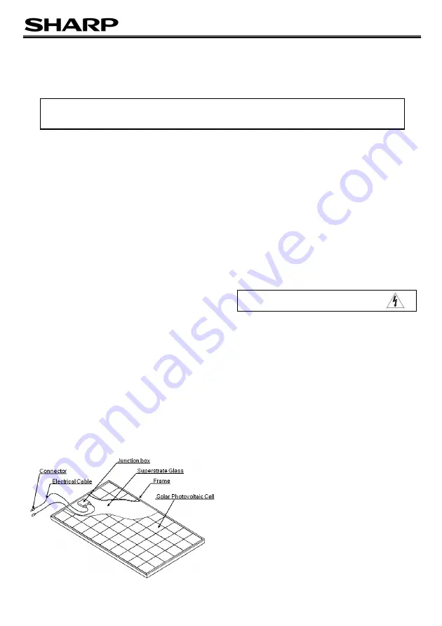
2. COMPONENTS
3. GENERAL INFORMATION
(INCLUDING WARNING AND SAFETY)
The installation of PV modules requires a great degree of skill
and should only be performed by a qualified licensed
professional, including licensed contractors and licensed
electricians. Please be aware that there is a serious risk of
various types of injury occurring during the installation including
the risk of electric shock. All SHARP PV modules are equipped
with a permanently attached junction box that will accept variety
of wiring applications or with a special cable assembly for ease
of installation, and they do not require special assembly.
GENERAL WARNING
1.
PV modules are heavy. Handle with care.
2.
Before you attempt to install, wire, operate and maintain
the PV module, please make sure that you completely
understand the information described in this installation
manual.
3.
Contact with electrically active parts of a PV module such
as terminals can result in burns, sparks and lethal shock
whether the PV modules are connected or not.
4.
PV modules produce electricity when the sufficient sunlight
or other sources illuminate the module surface. When the
modules are connected in series, voltage is cumulative.
When the modules are connected in parallel, current is
cumulative. As a result, a large-scale PV system can
MODEL
NU-AK300, NU-AK310, NU-AK300B
CAUTION: HIGH VOLTAGE
To reduce the risk of electric shock, do not touch.


