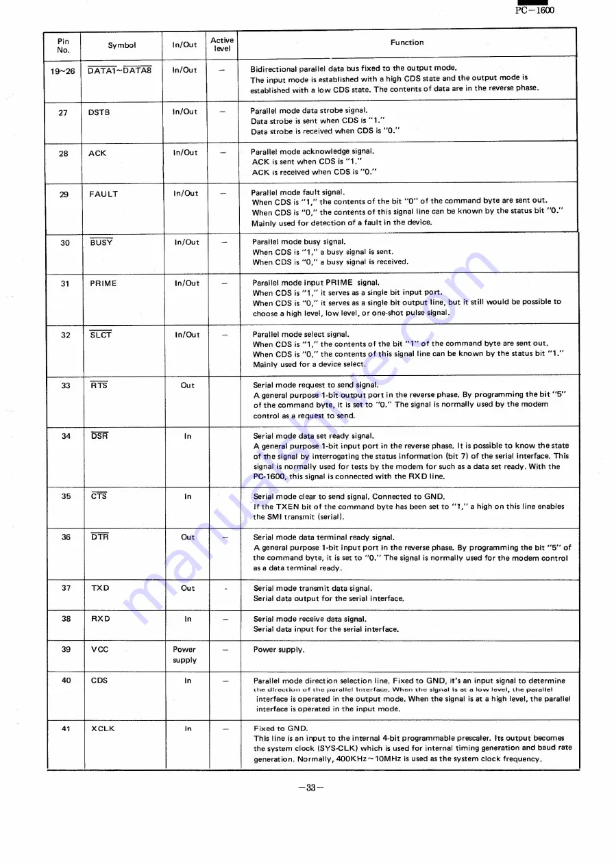
-
PC-1600
Pin
Symbol
ln/Out
Active
Function
No.
level
19-26
DATA1-DATAS
ln/Out
-
Bidirectional
parallel
data bus fixed
to the outpur
mode.
The input
mode
is established
with a high CDS state and the outpur
mode
is
established
with a low CDS state.
The contents
of data are in the reverse phase.
27
DSTB
ln/Out
-
Parallel
mode data strobe
signal.
Data strobe
is sent when CDS is "1."
Data strebe
is received
when CDS is "0."
28
ACK
ln/Out
-
Parallel
mode acknowledge
signal.
ACK is se nt when
CDS is "1."
ACK is received
when CDS is "0."
29
FAULT
ln/Out
-
Parallel
mode fault
signal.
When CDS is "1,"
the contents
of the bit "0" of the command
bvte are sent out.
When CDS is "0,"
the contents
of this signal line can be known
by the status
bit "0."
Mainly
used for detection
of a fault
in the device.
30
BUSY
ln/Out
-
Parallel
mode
busv signal.
When CDS is "1,"
a busv signal is sent.
When CDS is "0,"
a busy signal is received.
31
PRIME
ln/Out
-
Parallel
mode
input
PRIME
signal.
When CDS is "1,"
it serves as a single bit input
port.
When CDS is "0,"
it serves as a single bit outpur
line, but it still would
be possible
to
choose
a high level, low level, or one-shot
pulse signal.
32
SLCT
ln/Out
-
Parallel
mode select signal.
When CDS is "1,"
the contents
of the bit " 1" of the command
byte are sent out.
When CDS is "0,"
the contents
of this signal line can be known
by the status
bit "1."
Mainly used for a device select.
33
RTS
Out
Serial mode
request
to send signal.
A general
purpese
I-bit outpur
port in the reverse phase.
By programming
the bit "5"
of the command
bvte,
it is set to "0."
The signal is normally
used by the modem
control
as arequest
to send.
34
DSR
In
Serial mode data set ready
signal.
A general
purpose
1-bit input
port
in the reverse
phase.
It is possible
to know the state
of the signal by interrogating
the status
information
(bit 7) of the serial interface.
This
signal is normally
used for tests by the modem
for such as a data set ready.
With the
PC-1600,
this signal is connected
with the RX D line.
35
CTS
In
Serial mode
clear to send signal. Connected
to GND.
If the TXEN
bit of the command
bvte has been set to "1,"
a high on this line enables
the SMI transmit
(serial).
36
DTR
Out
-
Serial mode da ta terminal
ready
signal.
A general
purpese
t-bit
input
port
in the reverse
phase.
By programming
the bit "5"
of
the command
bvte,
it is set to "0."
The signal is normally
used for the modem
control
as a data terminal
ready.
37
TXD
Out
-
Serial mode
transmit
da ta signal.
Serial data output
for the serial interface.
38
RXD
In
-
Serial mode
receive data signal.
Serial data
input for the serial interface.
39
VCC
Power
-
Power supplv,
supply
40
CDS
In
-
Parallel
mode
direction
selection
line. Fixed to GND, it's an input
signal to determine
1:hedir-ection of the
por-allel
ece.
When '{he si9nal
ia
et
ZI
low level, the parallel
interface
is operated
in the outpur
mode.
When the signal is at a high level, the parallel
interface
is operated
in the input
mode.
41
XCLK
In
-
Fixed to GND.
This line is an input to the internal
4·bit
programmable
prescaler.
Its outpur
becomes
the system
clock
(SYS·CLK)
which
is used for internal
timing
generation
and baud
rate
generation.
Norrnallv,
400KHz-10MHz
is used as the system
clock
frequency.
-33-
Summary of Contents for PC-1600
Page 42: ... 11 CIRCUIT DIAGRAM PARTS POSITION KEY P W B LCD SIDE 39 ...
Page 43: ...PC l600 40 ...
Page 44: ...PC 1000 KEY P W B LSI SIDE 41 ...
Page 45: ... 42 ...
Page 48: ... PC l600 F P C P W B 45 ...
Page 49: ... Kn 46 ...
Page 52: ... PC l600 CONNECTOR P W B 49 ...
Page 53: ... 50 ...
Page 55: ... __ PC l600 tli I ONLY Pc 1600K I I 1 I 52 l J ...
Page 56: ... PC l600 K MEMORY P W B ROM Cut c IJ O lJ1F C O lJ1F I Bend capacitor to inward ROM SIDE 53 ...
Page 57: ...RAM SIDE 54 ...
Page 61: ...I I 2 3 4 42 58 ...
Page 93: ... P W B LSI SIDE t 90 ...
Page 117: ... PC I600 ...


