-
PC-l600
Step
Part No.
Component
6
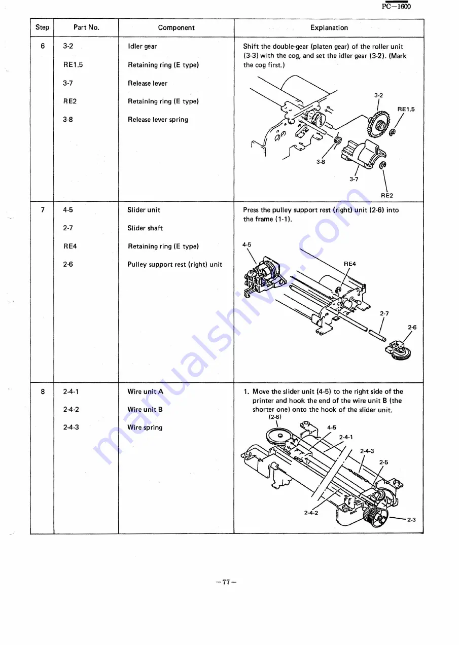
3-2
Idler gear
RE1.5
Retaining ring
(E
type)
3-7
Release lever
RE2
Retaining ring (E type)
3-8
Release lever spring
Explanation
Shift the double-gear (platen gear) of the roller unit
(3-3) with the coq, and set the idler gear (3-2). (Mark
the cog first.)
RE2
",
4-5
Slider unit
Press the pulley support rest (right) unit (2-6) into
the frame (1-1).
7
2-7
Slider shaft
RE4
Retaining ring (E type)
2-6
Pulley support rest (rightl unit
2-4-1
Wire unit A
8
2-4-2
Wire unit B
2-4-3
Wire spring
1. Move the slider unit (4-5) to the right side of the
printer and hook the end of the wire unit B (the
shorter one) onto the hook of the slider unit.
(2-6)
\
-77-
Summary of Contents for PC-1600
Page 42: ... 11 CIRCUIT DIAGRAM PARTS POSITION KEY P W B LCD SIDE 39 ...
Page 43: ...PC l600 40 ...
Page 44: ...PC 1000 KEY P W B LSI SIDE 41 ...
Page 45: ... 42 ...
Page 48: ... PC l600 F P C P W B 45 ...
Page 49: ... Kn 46 ...
Page 52: ... PC l600 CONNECTOR P W B 49 ...
Page 53: ... 50 ...
Page 55: ... __ PC l600 tli I ONLY Pc 1600K I I 1 I 52 l J ...
Page 56: ... PC l600 K MEMORY P W B ROM Cut c IJ O lJ1F C O lJ1F I Bend capacitor to inward ROM SIDE 53 ...
Page 57: ...RAM SIDE 54 ...
Page 61: ...I I 2 3 4 42 58 ...
Page 93: ... P W B LSI SIDE t 90 ...
Page 117: ... PC I600 ...

