oe
..,.
I
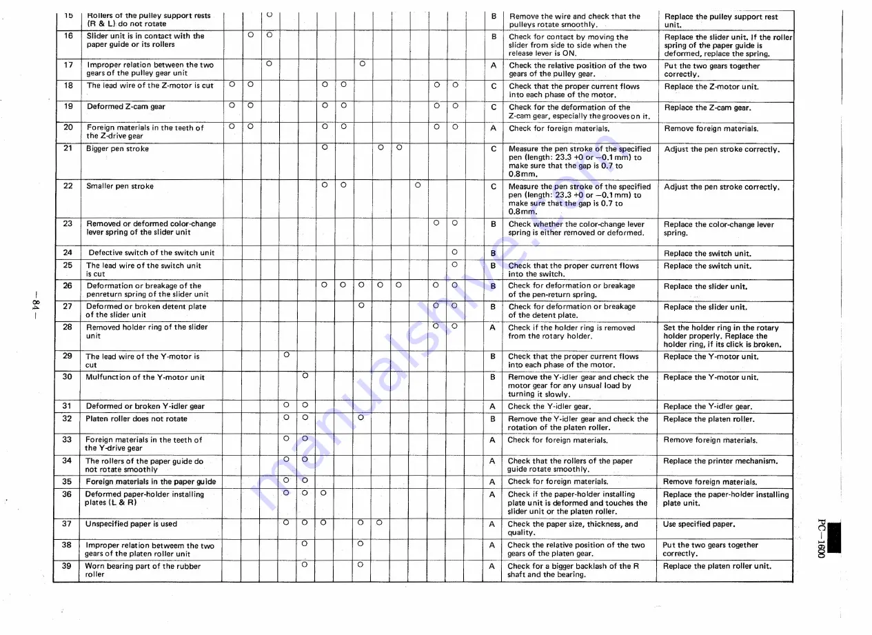
15
ROllers of the pulley
support
rests
0
B
Remove
the wire and check that the
Replace
the pulley support
rest
(R
&
L)
do not rotate
pulleys
rotate
smoothly.
unit.
16
Slider unit is in contact
with the
0
0
B
Check for contact
bv moving the
Replace
the slider unit.
If the roller
paper
guide or its rollers
slider from side to side when the
spring of the paoer guide is
release lever is
ON.
deformed,
replace
the spring.
17
Improper
relation
between
the two
0
0
A
Check the relative
position
of the two
Put the two gears together
gears of the pulley gear unit
gears of the pulley
gear.
correctly.
18
The lead wire of the Z·motor
is cut
0
0
0
0
0
0
C
Check that the proper
current
flows
Replace
the Z-motor
unit.
into each phase of the motor.
19
Deformed
Z·cam
gear
0
0
0
0
0
0
C
Check for the deformation
of the
Replace
the Z·cam
gear.
Z-cam gear, especially
thegrooveson
it.
20
Foreign
materials
in the teeth
of
0
0
0
0
0
0
A
Check for foreign
materials.
Remove
foreign
materials.
the Z-drive gear
21
B igger pen stro ke
0
0
0
C
Measure
the pen stroke
of the specified
Adjust
the pen stroke
correctly.
pen (length:
23.3
+0
or -0.1
mm) to
make sure that the gap is 0.7 to
0.8mm.
22
Smaller
pen stroke
0
0
0
C
Measure
the pen stroke
of the specified
Adjust
the pen stroke
correctlv,
pen (length:
23.3 +0 or -0.1
mm) to
make sure that
the gap is 0.7 to
0.8mm.
23
Removed
or deformed
color-change
0
0
B
Check whether
the
cotor-chanqe
lever
Replace
the color-change
lever
lever spring of the slider unit
spring is either
removed
or deforrned,
spring.
24
Defective
switch of the switch
unit
0
B
Replace
the switch
unit.
25
The lead wire of the switch
unit
0
B
Check that the proper
current
flows
Replace
the switch
unit.
is cut
into the switch.
26
Deformation
or breakage
of the
0
0
0
0
0
0
0
B
Check for deformation
or breakage
Replace
the slider unit.
penreturn
spring of the slider unit
of the pen-return
spring.
27
Deformed
or broken
detent
plate
0
0
0
B
Check for deformation
or breakage
Replace
the slider unit.
of the slider unit
of the detent
plate.
28
Removed
holder
ring of the slider
0
0
A
Check
if the holder
ring is removed
Set the holder
ring in the rotary
unit
from the rotary
holder.
holder
properly.
Replace
the
I
holder
ring, if its dick
is broken.
I
29
The lead wire of the Yrnotor
is
0
B
Check that the proper
current
flows
Replace
the Y-mctor
unit.
I
cut
into each phase of the motor.
30
Mulfunction
of the Y-rnotor
unit
0
B
Remove
the
Yvidler
gear and check
the
Replace
the V -motor
u nit.
rnotor
gear for any unsual
load by
I
turning
it slowly.
31
Deformed
or broken
V -idler gear
0
0
A
Check the V-idler gear.
Replace
the V-idler gear.
32
Platen
roller does not rotate
0
0
0
B
Remove
the Y-idler gear and check the
Replace
the platen
roller,
rotation
of the platen
roller.
33
Foreign
materials
in the teeth
of
0
0
A
Check for foreign
materials.
Remove
foreign
rnaterials,
the V -drive gear
34
The rollers of the paper guide do
0
0
A
Check that
the rollers of the paper
Replace
the printer
mechanism.
not rotate
smoothly
guide rotate
smoothly.
35
Foreign .materials
in the paper gu ide
0
0
A
Check for foreign
materials.
Remove
foreign
materials.
36
Deformed
paper-holder
installing
0
0
0
A
Check
if the paper-holder
installing
Replace
the paper-holder
installing
plates
(L
&
R)
plate unit is deformed
and touches
the
plate unit.
slider unit or the platen
roller.
37
Unspecified
paper
is used
0
0
0
0
0
A
Check the paper size, thickness,
and
Use specified
paper.
quality.
38
Improper
relation
betweem
the two
0
0
A
Check the relative
position
of the two
Pu t the two gears together
gears of the platen
roller unit
gears of the platen
gear.
correctly.
39
Worn bearing
part of the rubber
0
0
A
Check for a bigger backlash
of the R
Replace
the platen
roller unit.
roller
shaft and the bearing.
~I
Summary of Contents for PC-1600
Page 42: ... 11 CIRCUIT DIAGRAM PARTS POSITION KEY P W B LCD SIDE 39 ...
Page 43: ...PC l600 40 ...
Page 44: ...PC 1000 KEY P W B LSI SIDE 41 ...
Page 45: ... 42 ...
Page 48: ... PC l600 F P C P W B 45 ...
Page 49: ... Kn 46 ...
Page 52: ... PC l600 CONNECTOR P W B 49 ...
Page 53: ... 50 ...
Page 55: ... __ PC l600 tli I ONLY Pc 1600K I I 1 I 52 l J ...
Page 56: ... PC l600 K MEMORY P W B ROM Cut c IJ O lJ1F C O lJ1F I Bend capacitor to inward ROM SIDE 53 ...
Page 57: ...RAM SIDE 54 ...
Page 61: ...I I 2 3 4 42 58 ...
Page 93: ... P W B LSI SIDE t 90 ...
Page 117: ... PC I600 ...


