background image


xi 


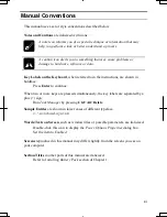
Manual Conventions 


This manual uses a set of style conventions described below. 


Notes and Cautions

 are italicized with icons: 


A note icon informs you of a special technique or information that may 
help you perform a task or better understand a process. 


A caution icon alerts you to something that may cause problems or 
damage to hardware, software or data. 


Key Labels on the Keyboard

, when referred to in the instructions, are shown in 

boldface: 
 Press 

Enter 

to continue.  

When two or more keys are pressed simultaneously, the key labels are separated by a 
plus (+) sign: 
 Run 

Task Manager

 by pressing 

Ctrl

+

Alt

+

Delete

Sample Entries 

are shown in lower cases of different typeface.   


c:\windows\system 


Words/Texts on Screen

, such as window titles or possible parameters, are italicized:  


Double-click this icon to display the 

Power Options Properties

 dialog box. 


Set the item to 

Enabled


Screens 

reproduced in this manual may differ slightly from the screens you see on 

your computer. 


Section Titles 

in other parts of this manual are italicized: 

 Refer 

to 

Installing Battery Pack 

section of Chapter 1.  


Summary of Contents for PC-MC20 Series

Page 1: ...PC MC20 Series OPERATION MANUAL DIC13th 641 C100 M60 Y0 K0 DIC 582 Black C0 M0 Y0 PK100 2 140P 6 3mm NOTEBOOK COMPUTER PC MC20 Series OPERATION MANUAL ...

Page 2: ...quipments off and on the user is encouraged to try to correct the interference by one or more of the following measures Reorient or relocate the receiving antenna Increase the distance between the equipment and receiver Connect the equipment into an outlet on a circuit different from that to which the receiver is connected Consult the dealer or an experienced radio TV technician for help A shielde...

Page 3: ...in advance that temporary discontinuance of service may be required But if advance notice isn t practical the telephone company will notify the customer as soon as possible Also you will be advised of your right to file a complaint with the FCC if you believe it necessary The telephone company may make changes in its facilities equipment operations or procedures that could affect the operation of ...

Page 4: ... To program this information refer to the manual of the communication software Warning This product utilizes tin lead solder and fluorescent lamp containing a small amount of mercury Disposal of these materials may be regulated due to environmental considerations For disposal or recycling information please contact your local authorities or the Electronics Industries Alliance www eiae org Copyrigh...

Page 5: ... VORSICHT UM DIE STROMZUFUHR VOLLSTÄNDIG ZU UNTERBRECHEN DEN NETZSTECKER HERAUSZIEHEN UND DIE BATTERIE ÈNTFERNEN ATTENTION POUR UN ARRET TOTAL DU SYSTEME DECONNECTEZ LA PRISE DE COURANT SECTEUR ET LA BATTERIE VARNING FÖR TOTAL ELEKTRISK URKOPPLING KOPPLA UR KONTAKTEN OCH TA UR BATTERIET PRECAUCION PARA UNA COMPLETA DESCONEXION ELECTRICA DESENCHUFE LA CLAVIJA DE LA RED Y LA BATERIA ...

Page 6: ...cold place to an extremely warm place A temperature difference of more than 10 C 18 F will cause condensation inside the unit which may cause damage Do not block or cover slots or openings on the cabinet These protect the computer from overheating Do not place the computer on unstable or uneven work surfaces Do not use the computer on your lap or any part of your body for an extended period during...

Page 7: ... DISCARD USED BATTERIES ACCORDING TO THE MANUFACTURER S INSTRUCTIONS Handling Never put the battery pack in a fire as it could explode and cause injury Do not attempt to open or alter the battery pack Do not place the battery where it might get hotter than 60 C 140 F Do not allow metal objects such as jewelry to short across the battery terminals as it could heat up and explode Do not allow liquid...

Page 8: ... Storage Store the battery pack in a cool and dry place Never allow the temperature to exceed 60 C 140 F during storage Recharge the stored battery pack after storage before use Wireless LAN Precautions Disable the integrated antenna and do not communicate with wireless LAN in specific environment where radio susceptible equipment is nearby such as on airplanes in hospitals etc ...

Page 9: ...t and any of its functions such as stolen credit card numbers the loss of or alteration of stored data etc Edition 1st Edition September 2003 Copyright 2003 SHARP Corporation This document contains or refers to proprietary information which is protected by copyright All rights are reserved Copying or other reproduction of this document is prohibited without the prior written permission of SHARP Co...

Page 10: ...ix All other brand and product names are trademarks or registered trademarks of their respective holders ...

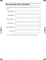
Page 11: ...e reference please record the following information in the spaces provided below Model Number Serial Number Date of purchase Dealer s Name Place of purchase Password The serial number is printed on a sticker located on the bottom of the computer ...

Page 12: ...dface Press Enter to continue When two or more keys are pressed simultaneously the key labels are separated by a plus sign Run Task Manager by pressing Ctrl Alt Delete Sample Entries are shown in lower cases of different typeface c windows system Words Texts on Screen such as window titles or possible parameters are italicized Double click this icon to display the Power Options Properties dialog b...

Page 13: ...xiv Quick Setup Installing Battery Pack 1 1 Connecting to AC Power Source 1 2 Setting Up Windows 1 4 Turning Off Your Computer 1 6 Basic Operations Choosing Power Source 2 1 Resetting System 2 3 Using Glide Pad 2 4 Using Keyboard 2 6 Using Optical Drive 2 7 Controlling Volume 2 13 Adjusting Display 2 14 Sharing Your Computer 2 16 Battery and Power Management Battery Pack 3 1 Power Management 3 7 ...

Page 14: ... Wireless LAN 5 9 Network Setup Utility 5 13 Setup Utility Running Setup Utility 6 1 Main Menu 6 3 Advanced Menu 6 4 Security Menu 6 4 Exit Menu 6 6 DirectHD Function DirectHD Utility 7 1 Connecting MC Series to Host Computer 7 3 Password Function 7 4 Disconnecting MC Series from Host Computer 7 6 Synchronizing MC Series with Host Computer 7 7 Appendixes Memory Module A 1 Maintenance and Care A 4 ...

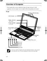
Page 15: ...ront Never turn off the computer when the hard disk indicator or the optical drive indicator is on This may damage the data on the hard disk Keyboard 2 6 Glide Pad 2 4 Power Button 1 3 Status Indicators Speaker Battery Indicator 2 1 3 3 Wireless LAN Antennas Power Indicator 1 3 2 1 A N LCD Screen 2 14 Antenna Indicator 5 9 Optical Drive Scroll Lock Caps Lock Num Lock Hard Disk ...

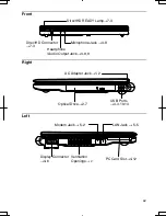
Page 16: ...o Output Jack 4 8 9 Optical Drive 2 7 AC Adapter Jack 1 2 USB Ports 4 3 10 14 LAN Jack 5 5 DirectHD Connector 7 3 PC Card Slot 4 12 Display Connector 4 6 Ventilation Openings v Modem Jack 5 2 DirectHD READY Lamp 7 3 Microphone Jack 4 9 ...

Page 17: ...xvi Rear Bottom Battery Pack 3 1 Cooling Fan v Security Hole A 8 USB Ports 4 3 10 14 ...

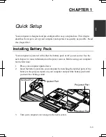
Page 18: ...the battery pack or AC power source See the next chapter for more information on the power sources Before using your computer for the first time 1 Place your computer upside down 2 Insert the battery pack into your computer by matching the notched parts of the battery to the projected parts on your computer and push the battery pack until you hear the clicking sound 3 Turn your computer over and g...

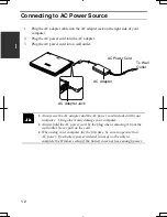
Page 19: ...d the AC power cord included with your computer Using others may damage your computer Always hold the AC power cord by the plug when removing it from the wall outlet Never pull on the cord When using your computer for the first time be sure to operate it on AC power If on battery power instead you may not be able to complete the Windows setup if the battery does not have enough power AC Adapter AC...

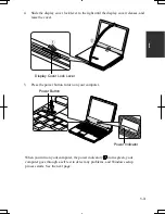
Page 20: ...raise the cover 5 Press the power button to turn on your computer When you turn on your computer the power indicator turns green your computer goes through a self test to detect any problems and Windows setup process starts See the next page Display Cover Lock Lever Power Indicator Power Button ...

Page 21: ...the Windows XP setup Do not connect any peripheral devices to your computer until Windows setup completes Otherwise your computer may malfunction If the display turns off some power management may function In this case press any key to resume your computer from the power management If you cannot operate the keyboard or the touch pad press the power button for more than four seconds to turn off you...

Page 22: ...f views Category view and Classic view The Category view allows you to choose the category that may be related to what you want to do then choose the task by clicking it The Classic view gives you the icons representing their components or features Double click one of the icons to open their dialog box or windows Some of the dialog boxes you will use often are Display Phone and Modem Options Mouse...

Page 23: ...ns Properties dialog box Close the cover to keep the screen and keyboard clean and protected If you have not saved a file a dialog box will appear asking whether you want to save it Do not turn off or reset your computer while the hard disk indicator or the optical drive indicator or the indicator on the optional external floppy disk drive unit is lit Doing so may damage or even wipe out the data ...

Page 24: ... battery information About Power Indicators The following indicators show the power status of your computer Indicator Light Meaning On green Operating Blinking green In System Standby Power Off Powered off or in System Hibernate On green Fully charged On orange Being charged Connected to AC Power Source Blinking orange In abnormal state Remove the battery pack and install it again Off Has power Ba...

Page 25: ... the battery The AC input voltage can range from 100 to 240 volts so that you can use your computer with the appropriate plug adapter The AC power cord included with your computer is appropriate for the voltage used in the area in which you purchased your computer If you attempt to connect your computer to a wall outlet other than in this area check the voltage of the outlet and use an AC power co...

Page 26: ...ystem by pressing the Ctrl Alt Del keys simultaneously and select Applications tab of Windows Task Manager dialog box Click the program name that hangs up then End Task If this does not solve the problem select User tab click Disconnect or Logoff of Windows Task Manager dialog box then Yes Power Switch You can turn off your computer with the power button if you encounter hardware or software probl...

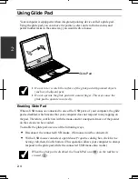
Page 27: ... connected to one of the USB ports of your computer the glide pad is disabled which means that your computer does not respond to any tapping on the pad Therefore confliction with the mouse and or unexpected move of the pointer on the screen can be avoided To enable the glide pad use one of the following ways Disconnect the connected USB mouse No mouse must be connected With a USB mouse connected o...

Page 28: ...st like that of a mouse Instead of clicking the left button you can also just tap gently anywhere on the rectangular pad For right clicking you must use the right button If the interval between clicks is too long the double click will not function Drag and Drop You can move the items by using drag and drop below 1 Position the pointer over the item you wish to move 2 Press the left button do not r...

Page 29: ... menu This key functions the same as the start button on the screen Application Key Opens short cut menus for the specific items This key functions the same as the right mouse button System Function Keys Your keyboard contains the function keys labeled F1 through F12 for special actions Use them in conjunction with Fn key Fn F1 Turns the wireless LAN antennas on and off Fn F3 Decreases the audio v...

Page 30: ... result in hazardous radiation exposure Maximum output and wavelength of the laser 108mW 784nm CD R RW 6mW 662nm DVD ROM CLASS1LASER PRODUCT LASER KLASSE1 Handling Disk Do not write on either side of the disk particularly the non label side Data is read write from onto the non label side Do not mark this surface Keep your disks away from direct sunlight heat and excessive moisture Always hold the ...

Page 31: ...dicator is not lit on then press the eject button The drive tray will pop out 2 Gently pull out the tray 3 Place your disk label side up onto the tray and slightly press the center of the disk until it locks into place Optical Drive Indicator Eject Button ...

Page 32: ...rough surface such as paper towels Instead use a cotton swab to gently wipe the lens Removing Disk 1 Make sure the optical drive indicator is not lit and press the eject button The optical drive tray will pop out Make sure the optical drive indicator is not lit before pressing the eject button 2 Gently pull out the tray 3 Remove the disk from the tray by holding its edge 4 Gently push the tray bac...

Page 33: ...ee space remains you can add data until the disk is full To write data run the application called Drag n Drop CD DVD installed on your computer See the online help of Drag n Drop CD DVD for the details To run Drag n Drop CD DVD click start All Programs Drag n Drop CD DVD Drag n Drop CD DVD Watching DVD Video You can enjoy watching DVD videos on your computer using the application called WinDVD See...

Page 34: ...o has a region code which prevents playback of the disk in certain regions The region code appears on the top of the disk When shipped from the factory your optical drive is set to a region code applicable to your area Your DVD drive region code can be changed Code change is limited Once the limit is reached it cannot be changed any more To confirm the limit click Region tab of Setup dialog box an...

Page 35: ...TSHITA xxxxxx xxxxxx is your optical drive name 4 Select DVD Region tab choose the listed distribution area of the DVD video then confirm the region code shown in the New Region field is correct and click OK 5 Read the message on the screen then click OK Using Parental Control If you want to set the parental control to prevent your children from watching an inappropriate movie follow the steps bel...

Page 36: ...close the dialog box then the Control Panel window You can also easily adjust the volume in the window that will open when clicking the speaker symbol on the taskbar When the symbol is not on the taskbar check the box of Place volume icon in the taskbar in the step 3 If you want to adjust the output volume of each source individually 1 Click start Control Panel 2 Click Sounds Speech and Audio Devi...

Page 37: ...ay Press and hold Fn key and then press F8 to maximizes the LCD screen brightness Pressing them again returns the LCD screen brightness to the previous status Changing Resolution and Number of Colors When shipped your computer is set to the default resolution and color The default resolution is 1024 x 768 at 64K colors To change the resolution and the number of colors follow the instructions below...

Page 38: ...K colors and High 24 bit means about 16 770 000 16M colors If you select High Drawing speed may be delayed When playing animation the screen may be distorted Changing Wallpaper and Setting Screen Saver You can enjoy various desktop patterns or screen savers Changing Wallpaper 1 In the Display Properties dialog box select Desktop tab 2 Select appropriate wallpaper in Background 3 Click OK Setting S...

Page 39: ...alog box then the Control Panel If more than one user account are set to your computer you must select which user account you will log in when you turn on your computer Log Off Your Computer Log off is useful because you do not have to turn off your computer when you finish your task and pass your computer to another person There are two ways to log off your computer Switch User or Log Off If you ...

Page 40: ...ick start Control Panel 2 Click User Accounts If Classic view is selected double click User Accounts icon 3 Select the account you want to set a password to You will only have this option if you log onto the computer as a member of the Computer administrators group If you log on your computer with a limited user account go to the next step You cannot set a password to another user account 4 Select...

Page 41: ...member the password you set 8 Click Change Password 9 Close the User Accounts dialog box then the Control Panel window Deleting Password 1 Follow the steps 1 2 on the Setting Password 2 Select the account you want to delete its password if you log on to your computer as a member of the Computer administrators group If you log on your computer with a limited account go to the next step You cannot d...

Page 42: ... s power management is active See the next section for power management To keep the battery life longer Condition the battery pack if the actual remaining power in your battery is less than what Windows Power Meter indicates See Conditioning Battery Pack section in this chapter Turn off your computer when you are not using it The duration of the battery depends on your computer usage Using applica...

Page 43: ...hen install the battery pack and connect the AC adapter again If the battery indicator still blinks orange ask your local dealer for assistance When the battery pack is hot for example after a long use it may take longer to be fully charged Checking Battery Level On Windows You can check the battery level by placing the pointer on the battery icon powered on battery or AC plug icon powered on AC p...

Page 44: ...r computer or connect the AC power source immediately Otherwise your computer will be shut down and the unsaved data may be lost On Windows you can set the battery level for sounding an alarm and letting your computer go on System standby System hibernate or shut down automatically To set Windows battery alarm 1 In the Power Options Properties dialog box select Alarms tab 2 Set the battery level a...

Page 45: ... computer to AC power and let the battery fully charged again Do not turn on your computer while charging the battery pack Do not connect your computer to a wall outlet while discharging the battery The conditioning will be cancelled Repeated charging and discharging or long term storage of the battery pack cause battery deterioration In this case replace the battery pack with a new one Changing B...

Page 46: ...unlocked position and hold them then push the battery pack 2 4 Insert the new battery pack into the computer by matching the notched part of the battery to the projected parts of the computer Notched Part Projected Parts Notched Part Battery Stoppers ...

Page 47: ...3 3 6 5 When the battery is properly inserted you will hear the click sound and the levers go back to their original positions ...

Page 48: ...ected double click Power Options icon Note that the power management may not seem to function when you are using an application program that accesses the hard disk periodically Stopping Power Supply to Hard Disk 1 In the Power Options Properties dialog box select Power Schemes tab 2 Set Turn off hard disks to an appropriate value and click OK 3 Close the Control Panel window Stopping Power Supply ...

Page 49: ...ance state will be chosen based on CPU demand Portable Laptop Using Battery Performance state will be chosen based on CPU demand Using AC Power Performance state will be chosen based on CPU demand Presentation Using Battery Always runs at lower performance state Using AC Power Always runs at highest performance state Always On Using Battery Always runs at highest performance state Using AC Power P...

Page 50: ...mentioned later In System standby the power indicator blinks green To resume from System standby operate your computer again System hibernate saves the current condition of your computer in part of the hard disk and turns off your computer Your system enters and resumes from System hibernate per the conditions mentioned later In System hibernate the power indicator is off To resume from System hib...

Page 51: ...dialog box select Power Schemes tab 2 From the pull down menu of System standby or and System hibernates select the elapsed time before your computer automatically enters System standby hibernate 3 Click OK 4 Close the Control Panel window Entering System Standby Hibernate Your computer enters System standby hibernate in each of the following cases You select Stand By or Hibernate which will repla...

Page 52: ...mputer field 3 Click OK 4 Close the Control Panel window If Ask me what to do is selected in the step 2 of You press the power button or You press Fn F12 the Turn off computer dialog box will appear when you press the power button or Fn F12 key combination You can select System standby or System hibernate at that timing The battery level is low The above functions if you set the alarm in Windows S...

Page 53: ...3 3 12 ...

Page 54: ...erals Your computer has connectors for peripheral devices shown on the next page For connection refer to the section explaining each device or contact your dealer Be sure to turn off your computer and the peripheral devices before connecting them except when connecting inserting USB devices a PC card etc Confirm the peripheral devices you will connect are Windows XP compatible When you connect som...

Page 55: ...rs for peripherals Connector Shape Connector name Connector shape USB Port External Monitor Port Headphone Audio Output Jack Microphone Jack Headphone Audio Output Jack USB Ports External Monitor Port Microphone Jack ...

Page 56: ...drive unit cable to one of the USB ports on your computer When connecting the cable to either of the USB ports on the right side of your computer be sure to let the USB mark side up and let the USB mark side down when using the USB ports on the rear side of your computer Handling Floppy Disk Do not open the shutter and touch the disk inside otherwise you will not be able to read or write data to t...

Page 57: ...rce when inserting the floppy disk If you have difficulty inserting or removing disks seek the assistance of an authorized service technician Do not touch the disk while reading writing data It may cause malfunction of your computer and the drive Ejecting Floppy Disk Before ejecting the floppy disk make sure the indicator of the floppy disk drive unit is not lit Press the eject button firmly The d...

Page 58: ...sk Drive Unit To remove the unit you need to perform the following steps before you remove it 1 Click Safely Remove Hardware icon on the taskbar 2 Click Safely remove Mitsumi USB Floppy Drive A then Safe To Remove Hardware dialog appears 3 Remove the unit from your computer External Display You can use an external monitor with your computer To display the images on both displays simultaneously use...

Page 59: ...cover when the connector is not used 3 Connect one end of the display cable to the display connector then the other end of the display cable to your external monitor If the display cable has screws be sure to tighten them 4 Turn on the external monitor then your computer Display Connector Display Cable supplied with the monitor or in the market Cover ...

Page 60: ...d button 2 Select S3Display tab then check the box of the desired output display s and click OK 3 Click OK in the Confirmation window 4 Click Yes in the Confirmation window 5 Click OK You can also switch the display with Fn F5 When you log on your computer as a member of the Limited group you cannot switch the display with the dialog box Use Fn F5 keys While playing video or animation you may not ...

Page 61: ...r computer Connecting Audio Equipment You can connect analog audio equipment to the audio output jack on your computer You can adjust the output volume on Windows by clicking the speaker symbol on the taskbar or use Fn F3 or F4 keys combination White Red LINE IN R LINE IN L Headphone Audio Output Jack Headphone Audio Output Jack Speakers with an Amplifier Stereo Mini Plug Stereo Mini Plug Analog A...

Page 62: ...cted to the microphone jack Use an electret condenser microphone with an impedance of 1 5 kΩ through 2 4kΩ and an allowable voltage of 2 5V To record sound 1 Click start then point All Programs Accessories Entertainment 2 Click Sound Recorder 3 See Help for Sound Recorder for more information Headphone Audio Output Jack Stereo Mini Plug Headphone Mini Plug Microphone Jack ...

Page 63: ...orrectly you will see the message on the screen In this case install the driver with the instructions on the screen The USB ports have different orientations according to the location on your computer Be sure to insert a USB cable in a correct orientation See the illustration below To remove USB devices you may need to perform the following instructions before you remove them 1 Click Safely Remove...

Page 64: ...led If the driver is not installed correctly you will see the message on the screen In this case install the PC card driver by following the instructions on the screen When you insert a protruding card such as wireless networking card Do not give force to the card otherwise your computer may be damaged Do not carry your computer with the card inserted otherwise your computer may be damaged 1 Confi...

Page 65: ...ing PC Card Some PC cards may become hot after long use Be sure to use the procedure below when ejecting a PC card Otherwise the system may not work properly 1 Click Safely Remove Hardware icon on the taskbar If you cannot find the icon click to show all kinds of icons 2 Click Safely remove xxxx xxxxx is the name of your PC card then Safe To Remove Hardware dialog appears Label Face Up ...

Page 66: ...rd eject button so that it will pop out from the side of your computer 4 Push the eject button until the inserted PC card pops out then remove it 5 Push the PC card eject button all the way inside the cabinet for safekeeping ...

Page 67: ... printer to your computer Some printer may not use Found New Hardware wizard to install the printer driver When connecting the cable to either of the USB ports on the right side of your computer be sure to let the USB mark side up and let the USB mark side down when using the USB ports on the rear side of your computer You can connect the USB printer to your computer without turning off your compu...

Page 68: ...e lines The modem may be damaged when connected to a digital ISDN terminal or a digital PBX Use TA terminal adapter to connect the built in modem to a digital telephone line If an unusual device is attached to the line you are connecting to the modem may not function properly Remove the device or contact the dealer of the device Before connecting to a PBX consult the PBX maintenance staff or its s...

Page 69: ... finish using the built in modem 3 Connect the core end of the included modem cable to the modem jack and the other end to the telephone line Be sure not to insert the modem cable into the LAN jack It may damage the LAN jack and the modem cable 4 Turn on your computer Connect the modem to the telephone line directly Do not use a distributor or allotter Modem Jack To Telephone Line Modem Cover ...

Page 70: ...Rules tab for the information you set above Clicking Edit or New allows you to make a new location or change the settings Internet Connection Windows XP has a special Internet connection wizard to help you to connect to the Internet with ease 1 Click start Control Panel Network and Internet Connections then Network Connections If Classic view is selected double click Network Connections icon 2 In ...

Page 71: ...aracteristics from those of the LAN cable Otherwise the LAN unit and the cables may be damaged Use a category 3 or a category 5 LAN cable when connecting to 10 BASE T LAN and the category 5 only when connecting to 100 BASE TX LAN Connecting Your Computer To LAN 1 Turn off your computer 2 Open the cover for the LAN jack on the left side of your computer To avoid damaging the LAN unit close the cove...

Page 72: ... administrator Make sure to log on your computer as a member of the Computer administrators group Otherwise you cannot set or change some settings for the LAN unit If you cannot access the network 1 Click start Control Panel 2 Click Performance and Maintenance then System If Classic view is selected double click System icon 3 Click Hardware tab then Device Manager button 4 Double click Network ada...

Page 73: ...twork Setup Wizard The Network Setup Wizard dialog box will open 2 Click Next 3 Click Next again When a message The wizard found disconnected network hardware appears With Local Area Connection string displayed in Connections field click Cancel to quit the wizard and confirm the other computer is powered on or the both computers are connected correctly with a cross cable Otherwise check the box of...

Page 74: ... Your Computer Name or Workgroup Name When you need to change your computer name or workgroup name follow these instructions 1 Click start My Computer 2 Click View system information in System Tasks field System Properties dialog box will open 3 Click Computer Name tab and Change button Computer Name Changes dialog box will appear 4 Type the Computer name and the Workgroup in each field and then c...

Page 75: ...g box will appear 2 Select Just enable file sharing and click OK 3 Check the box of Share this folder on the network and type the folder name to be shared in Share name field 3 Click OK The icon of the shared folder will be added a sharing symbol Copying Shared File 1 Click start Control Panel 2 Click Network and Internet Connections then Network Connections If Classic view is selected double clic...

Page 76: ...twork consists of a number of computers each equipped with wireless networking interface Each computer can communicate directly with other wireless enabled computers The range to give reliable performance and the quality of connection vary depending on the environment where you perform To communicate through the wireless LAN activate the integrated antennas with the following steps Activating Ante...

Page 77: ...f this connection of Network Tasks 4 Double click Internet Protocol TCP IP in This connection uses the following items 5 In Internet Protocol TCP IP Properties dialog box select Use the following IP address and set a unique IP address to 192 168 1 2 through 192 168 1 254 and the Subnet mask to 255 255 255 0 then click OK The IP address of each computer should be unique The Default gateway can be b...

Page 78: ...ion dialog box If the network requires the Network key entered go to Step 4 If it is not set Network key the caution message appears When the network name you want to access does not appear click Advanced tab then Refresh button of Available networks in Wireless Network Connection Properties dialog box then click OK 3 When you agree with the message check the box of Allow me to connect and go to S...

Page 79: ...network check the box of Allow me to connect to the selected wireless network even though it is not secure When the key index of your computer is different from that of the network you cannot access the network Set the same key index with the following steps Note that some access points have the key index options 0 through 3 Refer to the table below for matching 1 Open the Wireless Network Connect...

Page 80: ...Network Setup Utility 2 Click OK 3 Click Set select SHARP icon or Windows icon then click Select icon button 4 Select an icon and click OK Type a network name then click OK The selected icon appears in the Network Setup Utility window It takes a moment to load the network settings Switching Network To switch the network set above confirm your computer is ready to connect into the network and follo...

Page 81: ...ange the settings in the Network Setup Utility window and click Edit settings in the pop up menu Then edit the settings Deleting Network To delete the loaded network settings right click on the icon you want to delete in the Network Setup Utility window and click Delete setting in the pop up menu Then click OK ...

Page 82: ...n you have specified is saved in a special area called CMOS RAM which the system reads every time you turn on your computer Your computer is shipped from the factory with the appropriate setting of the Setup Utility Leave it as default in normal use Contents of Setup Utility The Setup Utility consists of four menu pages as follows Main Configures basic setting Advanced Configures device interface ...

Page 83: ...elect the menu 2 Use or key to select the item If the item has or _ Press Enter to enable or disable the item mark means the item is enabled Mark means disabled If the item has no mark except Date and Time of Main menu and Set Password of Security menu 1 Press Enter to open the sub menu 2 Use Tab key to highlight the value then use or key to select the value The value with is being selected 3 Use ...

Page 84: ...system cannot find the drive it will boot from the drive selected in 2nd Boot Device then the drive selected in 3rd Boot Device Internal NumLock defines whether the numlock keys of the built in keyboard are always disabled or not Num lock indicator will turn when Fn NumLk are pressed regardless of this setting An external keyboard will be numlocked if connected Hot Key Beep defines whether the bee...

Page 85: ...n LAN defines whether the system resumes from System Standby when the LAN unit of the computer becomes active Wake on Ring defines whether the system resumes from System Standby when the built in modem receives a call Security Menu Set Password defines the password up to eight characters See the next section about the password If you lose your password you will be unable to access your computer or...

Page 86: ...rm OK is highlighted and press Enter The system restarts Changing Password 1 In the Security menu of the Setup Utility select Set Password and press Enter 2 Type your current password and press Enter 3 Type your new password and press Enter 4 Type your new password again and press Enter twice 5 Select Exit menu and confirm Exit Saving Changes is highlighted then press Enter 6 Confirm OK is highlig...

Page 87: ...ut saving the settings you have changed Load Setup Defaults returns the values of all items to the default To exit select one of the above items Discard Changes returns the values of all items to the values you last saved To exit select one of the above two items Save Changes saves the settings you have changed To exit select one of the above two items ...

Page 88: ...d on DirectHD Utility To exchange data with your MC series and your host computer you need to install the DirectHD utility stored on the Product Recovery CD ROM Disk 3 into your host computer Follow these steps Supporting Operating System The DirectHD utility supports following operating systems Microsoft Windows XP Home Edition Microsoft Windows XP Professional hereafter called Windows XP Microso...

Page 89: ...rectHD Utility Be sure to install the application on your Host computer 1 Insert the supplied Product Recovery CD ROM Disk3 into the optical drive of your host computer 2 In My Computer double click the CD icon to open the CD ROM 3 Double click the DIRECTHD folder and setup icon to start the application installation 4 Follow the instructions on the screen 5 After the installation is successfully c...

Page 90: ...ur host computer may malfunction 1 Turn off your MC series You cannot exchange data between your MC series and your host computer when your MC series is powered on or in the standby hibernate mode 2 Connect the AC adapter to your MC series Be sure to connect the AC adapter in case the battery power becomes discharged In this case the connection will be stopped and unsaved data will be lost 3 Conne...

Page 91: ...rotect against unauthorized access to the hard disk of the MC series by the DirectHD function Setting Password Set a password of the MC series in the Setup Utility See Chapter 6 Canceling Password When a password is set to your MC series cancel the password temporarily to use your MC series as an external hard disk of your host computer 1 Connect your MC series to your host computer with the provi...

Page 92: ...s Windows XP or Windows 2000 Delete the password of the MC series in the Setup Utility See Chapter 6 When your host computer runs Windows Me 1 Cancel the password Refer to the previous section 2 Stop the device Refer to the next section 3 Remove the DirectHD cable from your computer 4 Delete the user password of the MV series in the Setup Utility See Chapter 6 Deletion of the user password without...

Page 93: ...e Safe To Remove Hardware dialog appears XX is a drive name of your MC series 3 Unplug the DirectHD cable from your MC series and host computer On Windows 2000 1 Click Unplug or Eject Hardware icon on the taskbar 2 Click Safely remove USB Mass Storage Device Drives XX XX XX is a drive name of your MC series 3 Click OK then unplug the DirectHD cable from your MC series and host computer On Windows ...

Page 94: ...ndows XP Microsoft Windows 2000 Professional hereafter called Windows 2000 Installing SharpSync Application and Setting Up Synchronization The SharpSync application is stored on the provided Product Recovery CD ROM Disk3 Be sure to install the application on your host computer 1 Connect your MC series and your host computer Refer to the Connecting MC series and Host Computer section in this chapte...

Page 95: ...etting up the synchronization the synchronized files will be recognized on your host computer whenever connecting your MC series with your host computer When installing other applications or software into your MC series be sure to directly install it You cannot install through your host computer 1 Turn on your MC series 2 Insert the CD ROM into the optical drive of your MC series 3 Follow the on s...

Page 96: ...nsion s by editing settings Follow the instructions below 1 Right click the SharpSync icon on the taskbar 2 Click Open Control Panel 3 Choose the Sync Set of which you want to change the condition 4 Click Edit Set 5 Click Filters then you can find the extensions that will be synchronized on the right side box 6 Choose a file extension you want to add to the synchronization target files from the le...

Page 97: ...7 10 7 ...

Page 98: ... body by touching an unpainted metal area Avoid touching the integrated circuits on a memory module Handle all components by the edges Keep the memory module in the anti static wrapping until you are ready to install it 1 Turn off your computer and disconnect the AC adapter and remove the battery pack and peripheral devices See Chapter 3 for removing the battery Make sure to turn off your computer...

Page 99: ...as shown below matching the notched part of the module with the projected part of the memory socket of your computer The cooling fan may be hot Be careful not to touch it when installing the memory module Notched Part Projected Part 20 Memory Slot Cover Screws Memory Module Slot Cooling Fan Slot ...

Page 100: ...ket until you hear the clicking sound 6 Replace the memory slot cover matching the projected parts of the cover with the notched parts of your computer 7 Tighten the screws 8 Replace the battery pack turn over your computer and connect the AC adapter See Chapter 3 for replacing the battery pack Notched Parts Projected Part Notched Parts Projected Parts Screws ...

Page 101: ...steps 6 9 of Installing Memory Module Maintenance and Care This appendix provides you with information on how to maintain your computer in excellent working condition Replacing Backup Battery Your computer is equipped a backup battery for keeping the information of the Setup Utility etc If you see the message Press F1 to Continue Del to Load CMOS defaults replace it with a new one Contact the Cust...

Page 102: ...ckup battery box 3 Remove the tape securing the cables and pull out the cable connecting the backup battery with your computer Pinch the cable as close to the connector as possible 4 Slowly remove the backup battery while lightly holding the sponge Cover Screws Tape ...

Page 103: ...eft 6 Insert the new backup battery to your computer with its tape side down into the pattern on the sponge and properly attach it with the adhesive tape 7 Secure the cables with the tape again and replace the cover on your computer matching the projected parts of the cover with the notched parts of your computer Notched Part Projected Parts Red Black Notched Part ...

Page 104: ... Press F1 to Continue Del to Load CMOS defaults It may take approximately one minute for this message to appear 13 Press the Delete key and Windows starts up 14 Click start Control Panel 15 Click Date Time Language and Regional Options in Category view then click on Change the date and time string 16 Set date and time then click OK 17 Close the Control Panel window ...

Page 105: ...ent theft Cleaning Computer Cabinet Apply a small amount of mild cleaning solution to a dry lint free cloth and wipe the cabinet with the cloth Never clean your computer while it is powered on Do not use alcohol benzene thinner or other strong chemical agents that may damage the cabinet Security Cable Security Slot ...

Page 106: ...aveling please follow these guidelines Before traveling back up your data on external media Do not travel with a protruding PC card inserted in the PC card slot of your computer Do not carry your computer powered on This may result in loss of data and or damage to the hard disk drive Make sure the display cover is completely closed before traveling Otherwise the cover may be opened unexpectedly an...

Page 107: ...A 10 Appendixes ...

Page 108: ... capable of generating errors and error messages If you encounter a software error try to determine if the error message is from your operating system or from an application program and refer to the appropriate manual for possible remedies You can also refer to the Windows manual or Windows help program to solve the problem To access the help program click start Help and Support It also gives you ...

Page 109: ...non bootable disk in the optional external floppy disk drive unit either a defective disk or one without an installed operating system Remove the disk Question Why can t I boot from the floppy disk Make sure that the optional external floppy disk drive unit is correctly connected to your computer Check whether the floppy disk set to the optional external floppy disk drive unit contains a system di...

Page 110: ...is correctly installed and has a charge remaining Make sure the LCD screen is selected as the display by pressing Fn F5 Check whether the display is on by pressing Fn F11 If you still have the problem after trying the above follow the steps in Why doesn t the keyboard or the glide pad function Question Why does the external monitor display nothing or the image on it distorted Confirm the monitor i...

Page 111: ...Delete and select Applications tab of Windows Task Manager dialog box Click the program name that hangs up then End Task If this does not solve the problem select User tab click Disconnect or Logoff of Windows Task Manager dialog box then Yes 2 If the step1 fails to work press the power switch for more than four seconds to turn off the system Ten seconds later turn your computer on 3 If pressing t...

Page 112: ...e another disk Trouble with the Hard Disk Question Why can t I read or write data to from the hard disk Confirm the drive and file names are correct Confirm the hard disk has sufficient free space Trouble with the Optical Drive Question Why can t I read data from a compact disc or play files Confirm the CD is inserted correctly Confirm the drive and file names are correct Confirm the CD is not sta...

Page 113: ...ive then turn on your computer again Trouble with Communication Question Why can t I communicate through the built in modem Confirm the telephone line is properly connected to the modem jack Confirm the dial setting pulse or tone of Windows XP and or communication software is matched with the telephone line If you set your connection status using New Connection Wizard check Use dialing rules in th...

Page 114: ...ess point on my computer Confirm the access point is powered on Confirm the antenna indicator is lit Restart your computer Confirm your computer is enabled for the wireless LAN Detect the access point with the following steps 1 Click start Control Panel 2 Click Network and Internet Connections Network Connections In Classic view double click Network Connections icon Network Connections dialog box ...

Page 115: ...net Connections Network Connections If Classic view is selected double click Network Connections 3 Right click Wireless Network Connection and click Properties 4 Click Wireless Networks tab select the network in Preferred networks field and click Properties button 5 Select Authentication tab then uncheck the box of Enable IEEE802 1x authentication for this network 6 Click OK twice and close the wi...

Page 116: ...al Area Connection section for LAN or Ethernet adapter Wireless Network Connection section for Wireless LAN Type exit then press Enter Trouble with Peripherals Question Why don t peripheral devices function Confirm they are correctly connected to your computer Confirm they are Windows XP compliant Confirm drivers necessary for the devices are installed Question Why can t I print Make sure the prin...

Page 117: ...nd does not have enough battery power it cannot be recognized as an external hard disk Connect the AC adapter and reconnect the DirectHD cable Reconnect DirectHD cable You may not have stopped the connection properly When using a USB hub connect an AC adapter to the hub Question Why is my MC series recognized as a removable disk or why cannot I access it through my host computer When you have set ...

Page 118: ...d to your host computer may cause it Press F5 key This may not work properly due to the setting condition or the installed operating system in your host computer Question Why does a message Please insert a disk drive appear Your MC series may be still set the user password Cancel the password using the Password Utility of the DirectHD utility Refer to the Canceling Password section in Chapter 7 Ot...

Page 119: ...3 Double click the device you cannot use and confirm Use this device enable appears in Device usage Question Why can t I produce sound Click or double click the speaker symbol on the taskbar and check the Windows volume Question Why can t I turn off my computer Follow the instructions on Why doesn t the keyboard or the glide pad function Question Why my computer is so hot When charging the battery...

Page 120: ...alog box Question Why can t find the drivers and applications You may accidentally remove them They are stored on the last recovery disk i e when three recovery CDs are provided they are stored on the Disk 3 When you are not sure how to install them or the CD does not have the drivers or applications consult local service staff ...

Page 121: ...Troubleshooting T 14 ...

Page 122: ...puter 7 3 disconnecting from host computer 7 6 password function 7 4 synchronizing with host computer 7 7 Display changing brightness 2 14 changing resolution 2 14 changing number of colors 2 14 switching the display 2 6 4 7 troubleshooting T 3 turning off 2 7 E External monitor connecting 4 6 disconnecting 4 7 switching the display 2 6 4 7 F File sharing copying 5 8 sharing 5 8 Floppy disk connec...

Page 123: ... Optical Drive Using 2 7 Troubleshooting T 5 P Passwords changing 2 18 6 5 deleting 2 18 6 5 setting 2 17 6 5 PC cards ejecting 4 12 inserting 4 11 Peripherals audio equipment 4 8 connecting guidelines 4 1 external monitor 4 5 headphones 4 9 PC cards 4 11 printer 4 14 speaker 4 8 troubleshooting T 9 USB device 4 10 Power choosing AC or battery 2 1 indicator 1 3 2 1 Power management disabling 3 11 ...

Page 124: ...9 generating conditions 3 10 resuming from 3 9 supporting 3 10 Status indicators xiv T Troubleshooting common problems T 1 communications T 6 CD T 5 DirectHD T 10 display T 3 floppy disk drive T 4 hard disk drive T 5 keyboard or glide pad T 4 peripherals T 9 wired LAN T 7 wireless LAN T 7 U USB device 4 10 W Wallpaper 2 15 Wireless LAN activating antenna 1 4 5 9 communicating 5 10 confirming statu...

Page 125: ...Index 2 Index ...

Page 126: ...SHARP CORPORATION PC MC20 Series OPERATION MANUAL 0 09x Page 2 140P ...

Reviews: