background image

Hardware Expansion  6-5

6

3.

Remove the memory module from its wrapping.

4.

Hold the memory module so that its edge connector is facing the socket. Make
sure the notch on the corner of the memory module mates with the notch on the
socket.

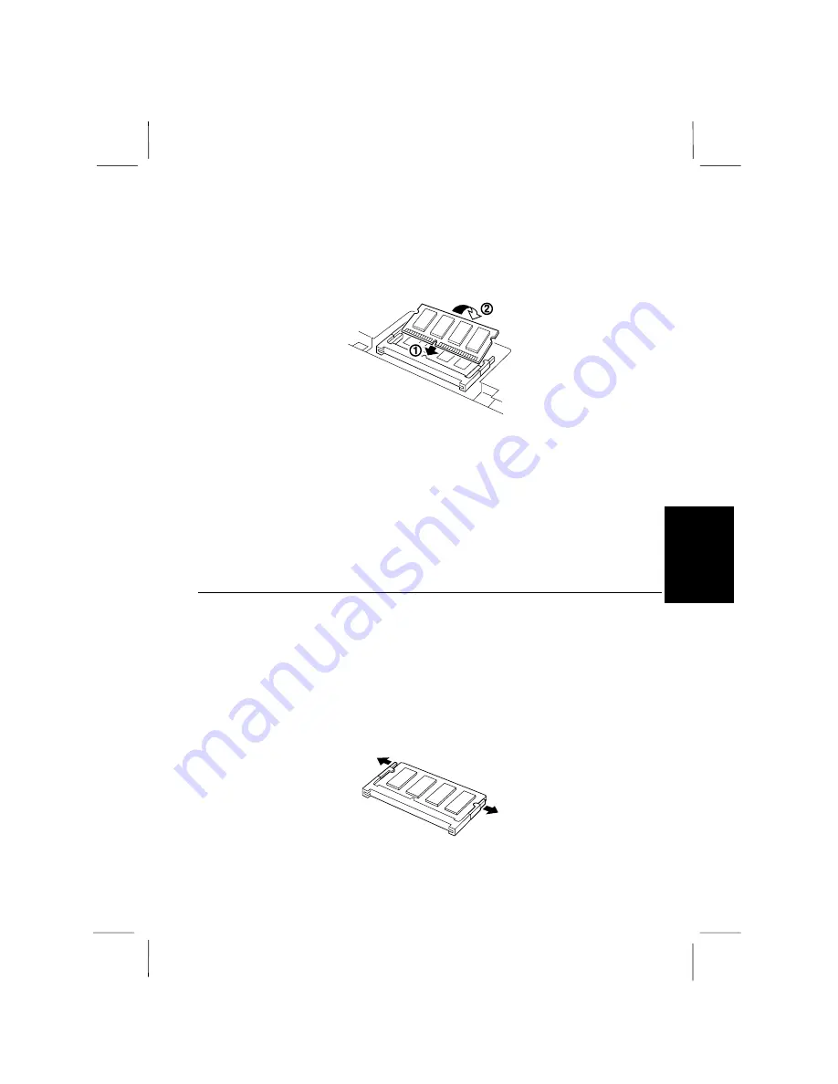
Figure 6-3. Securing the Memory Module

5.

Insert the memory module into the socket and gently push it until it is firmly
seated (

).

6.

Slowly move the memory module to a horizontal position until the locking tabs
snap into the retaining notches or holes at each end of the module (

).

7.

Replace the keyboard and push back the locking knobs.

Removing a Memory Module

Follow the steps below to remove a memory module:

1.


Turn off the notebook and unplug the AC adapter.

2.


Open the keyboard as described in the previous section.

3.


Remove the locking tabs from the memory module at the same time until the
memory module comes out of the notches. Gently move the memory module
upward and remove it.

Figure 4. Removing the Memory Module

Summary of Contents for PC-W100 Series

Page 1: ... determined by turning the equipment off and on the user is encouraged to try to correct the interference by one or more of the following measures Reorient or relocate the receiving antenna Increase the distance between the equipment and receiver Connect the equipment into an outlet on a circuit different from that to which the receiver is connected Consult the dealer or an experienced radio TV te...

Page 2: ...ify you in advance that temporary discontinuance of service may be required But if advance notice isn t practical the telephone company will notify the customer as soon as possible Also you will be advised of your right to file a compliant with the FCC if you believe it necessary The telephone company may mark changes in its facilities equipment operations or procedures that could affect the opera...

Page 3: ...a 900 number or any other number for which charges exceed local or long distance transmission charges To program this information refer to the manual of the communication software CAUTION Danger of explosion if battery is incorrectly replaced Replace only with the same or equivalent type recommended by the manufacturer Discard used batteries according to the manufacturer s instructions Copyright I...

Page 4: ...certified connector assembly telephone extension cord The customer should be aware that compliance with the above conditions may not prevent degradation of service in some situations Repairs to certified equipment should be made by an authorized Canadian maintenance facility designated by the supplier Any repairs or alterations made by the user to this equipment or equipment malfunctions may give ...

Page 5: ...nt that the total of the Load Numbers of all the devices does not exceed 100 This digital apparatus does not exceed the Class A Limits for radio noise emissions from digital apparatus as set out in the Radio Interference Regulation of the Canadian Department to Communications Product Information and Customer Assistance For Product Information and Customer Assistance Call 1 905 890 2100 Sharp Elect...

Page 6: ...y is incorrectly replaced Replace only with the same or equivalent type recommended by the manufacturer Do not dispose of large quantities of used Lithium batteries at the same time Copyright Copyright may exist in material you wish to record Copying or broadcasting such material without permission of the relevant licensees or owners of the copyright is prohibited by law SHARP is not in a position...

Page 7: ...nnected to the terminal which is marked with the letter L or coloured red This apparatus must be protected by a 3A fuse in the mains plug or distribution board WARNING THIS APPARATUS MUST BE EARTHED This apparatus is approved under approval number NS G 1234 J 100003 for indirect connection to the public telecommunication system in the United Kingdom Copyright Recording and playback of any material...

Page 8: ...elle direttive 89 336 EEC e 73 23 EEC come emendata dalla direttiva 93 68 EEC Η εγκατασταση αυτη ανταποκρινεται στιζ απαιτησειζ των οδηγιων τηζ Ευρωπαïκηζ Ενωσηζ 89 336 EOK κατ 73 23 EOK óπωζ οι κανονισµοι αυτοι συµπληρωθηκαν απó την οδηγια 93 68 EOK Este equipamento obedece às exigências das directivas 89 336 CEE e 73 23 CEE na sua versão corrigida pela directiva 93 68 CEE Este aparato satisface ...

Page 9: ...HE BATTERY VORSICHT UM DIE STROMZUFUHR VOLLSTÄNDIG ZU UNTERBRECHEN DEN NETZSTECKER HERAUSZIEHEN UND DIE BATTERIE ÈNTFERNEN ATTENTION POUR UN ARRET TOTAL DU SYSTEME DECONNECTEZ LE FIL DE LA BATTERIE VARNING FÖR TOTAL ELEKTRISK URKOPPLING KOPPLA UR KONTAKTEN OCH TA UR BATTERIET PRECAUCION PARA UNA COMPLETA DESCONEXION ELECTRICA DESENCHUFE LA CLAVIJA DE LA RED Y LA BATERIA ...

Page 10: ...lled on the notebook if the notebook has been dropped or the cabinet has been damaged Never push any objects of any kind into cabinet openings They may touch dangerous voltage points or short parts that could result in fire or electrical shock Turn off the notebook before installing or removing a peripheral device Turn off the notebook and disconnect the AC cord before cleaning Do not expose the n...

Page 11: ...ort circuiting However covering or pressing this breaker switch hard could cause the battery to malfunction Do not allow liquids to come in contact with the battery pack Avoid dropping the pack or other violent shock Do not solder to the battery terminals Charging Charge the battery pack only with the notebook s built in AC adapter Discharging Do not use the battery pack for any purpose other than...

Page 12: ... as stolen credit card numbers the loss of or alteration of stored data etc Edition 1st Edition August 1996 Copyright 1996 Sharp Corporation This document contains or refers to proprietary information which is protected by copyright All rights are reserved Copying or other reproduction of this document is prohibited without the prior written permission of Sharp Corporation Trademarks Pentium is a ...

Page 13: ...aces provided below Model Number Serial Number BIOS Version Number Date of purchase Dealer s Name Place of purchase Password The serial number is printed on a sticker located on the bottom of the notebook You will see the BIOS Version number on the middle line of the LCD screen when you turn on the notebook ...

Page 14: ...ies of the notebook Topics cover printer external monitor keyboard mouse and audio equipment Chapter 5 Communication Functions Discusses the infrared communication and the modem Chapter 6 Hardware Expansion Describes using PCMCIA cards and increasing memory Chapter 7 Using the Passwords Discusses how to use the password to protect data stored in your notebook Chapter 8 Setup Utilities Describes ho...

Page 15: ...Del This means hold down the Ctrl and Alt keys and press Del simultaneously Important key combinations are highlighted throughout this manual by enlarged and iconic representations of the keys you must press to perform an operation e g Fn F5 Notes and Cautions Icons and italicized text are used for notes and cautions to make important information stand out An information icon alerts you to a speci...

Page 16: ...e press the Enter key after you type the command C FORMAT A Enter Note that the screens reproduced in this manual may differ slightly from the screens you see on your notebook File Names References to commands utilities device drivers directory and file names in this manual are printed in upper case as shown below Type in the PHDISK command Section Titles Section titles in other parts of the manua...

Page 17: ...uick Setup Your notebook is designed and pre configured for easy setup and use This chapter describes the steps you should follow to get up and run the notebook as quickly as possible You should read this chapter first ...

Page 18: ......

Page 19: ... below 1 Make sure the notebook is turned off 2 Connect the AC adapter cord to the notebook À 3 Connect the AC power cord to the AC adapter Á Always use the AC adapter supplied with the notebook EA W100V Using other AC adapters may damage the notebook Always hold the AC adapter cord by its plug 4 Plug the AC power cord into a wall outlet  Figure 1 1 Connecting to AC Power Before using the battery...

Page 20: ...t end of the screen cover The latch locks the cover in the closed position when the notebook is not in use To raise the cover follow these steps 1 Slide the display lock latch until the screen cover releases and then raise the cover 2 Tilt the cover to a comfortable viewing position Figure 1 2 Opening the Screen Cover ...

Page 21: ...Power On While Starting Windows 95 appears pressing F8 allows you to choose how to start Windows 95 For details see the Windows 95 documentation as well as the Windows 95 Help files Do not turn power off immediately after turning it on Instead wait several seconds When the power is turned on the power indicator lights and the notebook goes through a self test to detect any problems When this is co...

Page 22: ... the notebook Adjusting the Screen Brightness decreases the screen brightness increases the screen brightness turns the LCD backlighting on or off Adjusting Sound Volume Use the audio volume control on the right side of the notebook to adjust the speaker volume Turn it away from you to increase the volume or towards you to decrease the volume ...

Page 23: ... agreement displayed in the screen Click I accept the agreement if you accept Then click Next 6 Certificate of Authenticity See the Certificate of Authenticity on the front cover of the Microsoft Windows 95 manual which came with your notebook Type the number shown above the bar code on your Certificate of Authenticity and then click Next to continue 7 Configuring the Computer Now Setup has enough...

Page 24: ...port you want to use with this printer and then click Next All your Windows based programs will use this printer as the default printer 12 Print a test page After your printer is installed Windows can print a test page so you can confirm that the printer is set up properly Then Setup installs the printer driver which is appropriate for the selected printer 13 Time Zone Select the time zone where y...

Page 25: ...isks you may not be able to recover your system or personal data We strongly recommend that you use high quality floppy disks and store these disks in a secure place Creating System and Application Disks Creating disks for Windows 95 and pre installed applications Application floppy disks generated by MSCSD Microsoft Create System Disks are as follows Microsoft Windows 95 Setup Disks 31 disks Nets...

Page 26: ...ing the power management Audio Driver Setup Disks Use to restore audio driver appropriate for your notebook Windows 95 S3 Driver Disk Use to restore S3 display driver ALPS GlidePoint Driver Disk Use to restore ALPS GlidePoint Driver Sharp Support Disks Use to restore the GlidePoint Control utility Infrared driver and PCM 3 2 PCMCIA Card driver for MS DOS Sharp Data Disk Use to restore the Sharp On...

Page 27: ...Setup Disks but the labels of the other Setup Disks are not provided with your notebook After you completed to make all the Setup Disks except the Windows 95 Startup Disk you will see the dialog box to finish creating system disks then click Finish and the Microsoft Create System Disks will appear nowhere Windows 95 Startup Disk can be made from the Control Panel From the Control Panel double clic...

Page 28: ...ouble click the Sharp Startup icon at the upper right corner of the screen 2 When the message appears click OK The next time the computer is restarted several programs are set in the StartUp folder and the SHARP original wallpaper is displayed on the screen as default The instructions in the documents attached to the notebook assume that you have set the initial condition ...

Page 29: ...ou want to save it or not While the hard disk or floppy disk drive indicator is lit do not turn off the power or reset the notebook Doing so may damage or even wipe out the data To protect the screen always close the screen cover when the power is turned off Before turning it back on wait at least 10 seconds after turning off the notebook Turning the power off and on in rapid succession can damage...

Page 30: ... not damage the system you may lose the data you are processing Power Switch You can turn off the notebook with the power switch if you encounter hardware or software problems which lock up the system Press the power switch for more than five seconds The notebook will shut down Hardware Reset You should use the hardware reset switch only if the power switch does not turn off the notebook The switc...

Page 31: ...C H A P T E R 2 Basic Operations This chapter describes the basic operations you can perform on the notebook ...

Page 32: ......

Page 33: ...nd to Disk mode or the power is off For more information see Chapter 3 on Suspend to RAM and Suspend to Disk modes Using the AC Adapter The AC adapter provides power for operation and to charge the battery when the AC adapter is connected to a wall outlet The AC input voltage can range anywhere from 100 to 240 volts making it suitable for use virtually anywhere in the world with the appropriate pl...

Page 34: ...ou plug in into a wall outlet this means the battery pack is not charged yet Simply proceed to step 2 immediately Also if Press F1 to resume F2 to SETUP appears after the notebook is turned on this means the setup contents have changed Press F2 then press Enter When the Setup Utility screen appears press Esc then Enter twice to restart the system again Charging the Battery To recharge the battery ...

Page 35: ...e warning beeps continues for 10 seconds Blinking red The battery power is almost gone The warning beeps continues while the notebook automatically enters the suspend to disk mode Checking the Battery Level Check the battery level as follows 1 From the Start menu select Control Panel 2 Double click Power and read the battery level The remaining battery amount and remaining time are estimates based...

Page 36: ...ong time and should recharge it fully before use If the battery is fully charged and left unused for a long time The battery will discharge itself slowly and The life of the battery will be shortened Lithium ion batteries do not have so called memory effect and you do not have to deep discharge the battery pack before charging it Disposing of Battery Packs The capacity of a battery pack is gr adua...

Page 37: ... software applications will require use of the left button Do not hit or scratch the surface of the GlidPoint with pointed objects such as ballpoint pen Do not operate the GlidePoint with wet or sweaty hand otherwise the GlidePoint may not operate correctly Using the GlidePoint Take a moment to become familiar with how the GlidePoint works Figure 2 1 The Integrated GlidePoint Place Your Fingertip ...

Page 38: ...raditional pointing device the whole pad acts as if it were a left button and each tap on the pad is equivalent to pressing the left button If you swap the left and right buttons tapping on the GlidePoint as an alternative method of pressing the left button will no longer function Drag and Drop You can execute commands or move files by using drag and drop In drag and drop you activate a file by po...

Page 39: ...ou should familiarize yourself with the special notebook function keystrokes which allow you to quickly and easily control and adjust such features as display brightness and access to power management Figure 2 2 Keyboard Layouts Windows Logo Keys opens the Windows Start menu provides application specific short cut menu equivalent to the right button ...

Page 40: ...rred to as hot keys toggles between video display output to the LCD screen SimulScan display on the LCD and external CRT monitor and the CRT decreases the LCD screen brightness increases the LCD screen brightness Fn F8 and Fn F9 do not function turns the screen backlighting on or off puts the notebook in suspend mode to RAM or to Disk according to the setup selection To resume normal operation fro...

Page 41: ...DD 720KB or high density 2HD 1 44MB floppy disk Handling Floppy Disks Do not open the shutter and touch the disk inside otherwise you will not be able to read or write data to the disk Do not place floppy disks near magnets and the like direct sunlight a heat register or in dusty place Do not leave floppy disks on the built in speakers the magnets inside the speakers may destroy the disks Never su...

Page 42: ...into the printer floppy disk drive connector on the back of the notebook Then plug the small connector into the external keyboard and PS 2 mouse port Figure 2 4 Connecting a Floppy Disk Drive When turned on the notebook will be able to recognize the floppy disk drive automatically When inserting a floppy disk into the notebook make sure it is not upside down Also do not subject the disk to sudden ...

Page 43: ... Inserting a Floppy Disk Always insert a floppy disk straight into the notebook When inserting the disk into the notebook make sure it is not upside down Do not push the disk into the notebook by excessive force Removing Make sure the floppy disk drive indicator is off Press the eject button to pop out the disk slightly then remove it and store it away properly Figure 2 6 Ejecting a Floppy Disk In...

Page 44: ...ws 95 has a backup function to let you easily back up your data From the Start menu select Programs Accessories System Tools Backup to start the backup operation For more information use the Windows 95 Help Backup method may differ depending on software in use Windows 95 Startup Disk You need this disk only when you want to use the notebook if the notebook cannot start for any reason It starts up ...

Page 45: ...C H A P T E R 3 Power Management and Battery This chapter explains how to better manage the notebook s power and use additional battery packs ...

Page 46: ......

Page 47: ... Settings You can configure power management settings using the Power menu of the Setup Utility Power settings allow you to control current drain by peripheral devices and put them in suspend mode when not in use By continually monitoring the state of these devices and shutting off the flow of current to idle devices battery life can be preserved You can access the Power menu of the Setup Utility ...

Page 48: ... a resume event occurs while the hard disk drive powers back up LCD Backlight Allows you to select the brightness of the LCD Backlight Possible values include Bright Standard or Dim Suspend Mode Allows you to select when a suspend event occurs Suspend to RAM the default or Suspend to Disk The exceptions are the notebook suspends to RAM for cover switch event and suspends to disk for critical batte...

Page 49: ...Suspend Mode option in the Setup Utility Suspend to RAM When the notebook suspends to RAM an alerting beep sounds and the state of the notebook is stored to RAM All but a few essential components of your notebook power down Pressing any key allows the notebook to return to exactly the same state it was in when suspend mode was activated You can use Suspend to RAM when you have to pause your comput...

Page 50: ...nstalled memory When you enter or resume from Suspend to Disk mode you can see some flicker on the display However this is not a malfunction Entering Suspend Mode Suspend mode can be activated in any of the following ways By clicking Suspend on the Windows Start menu By pressing Fn F12 By setting the Auto Suspend option in the Setup Utility to automatically suspend after a certain period of notebo...

Page 51: ...tem to Enabled When using a PC Card set the PCMCIA Power when Suspend to RAM item to Enabled Resuming from Suspend Mode Normally resuming from a suspend mode is triggered as follows By the power switch If Suspend to RAM is active by pressing any key or by calling up the modem Also if the suspend state was entered by closing the cover operation resumes when the cover is opened as long as battery vo...

Page 52: ...the AC adapter as well as any peripherals in use 2 Close the screen cover Place the notebook on a flat surface then turn it upside down so that the front is facing you 3 Slide out the two battery locks as shown then gently lift up the battery pack Figure 3 2 Removing a Battery Pack 4 Insert another battery pack into the notebook making sure the four tabs on the battery pack go right into the groov...

Page 53: ...arge it like the standard battery you can also use the optional battery charger CE W10CH to charge it See the section below for more information Using the Battery Charger You can use the optional battery charger CE W10CH to charge the battery packs Installing a battery pack 1 Insert the 2 inner tabs on the battery pack into the grooves on the battery charger so that the battery pack clicks into pl...

Page 54: ...Charging Blinking orange An error occured Fully charging a new battery pack takes about three hours If the battery indictor blinks in orange an error has occurred during the charge Therefore remove the battery pack then replace it again Removing the Battery Pack 1 Unplug the AC adapter from the battery charger 2 Push the battery lock on the sides of the charger then gently lift up the battery Figu...

Page 55: ... chapter describes how to attach optional devices to your notebook You can attach a printer connect an external monitor or keyboard a mouse or any other peripheral device that connects to a parallel serial or PS 2 keyboard mouse port ...

Page 56: ......

Page 57: ... with compliant printers However you need the special printer drivers to use EPP protocols Connecting a Printer To connect a printer to the notebook follow these steps 1 Be sure both the notebook and the printer are turned off 2 Open the I O port cover at the rear of the notebook with your finger and locate the ports labeled parallel and serial 3 If you are using a parallel interface connect the 2...

Page 58: ...cted to the notebook and then turn on the notebook 6 If necessary run the notebook s Setup Utility to configure the parallel port to respond as required by your printer and software operating environment Installing the Printer Driver The newly connected printer must be configured in Windows Refer to the Windows 95 Help for details on setting up a printer You can also refer to your printer manual f...

Page 59: ...T connector 3 Connect the appropriate end of the monitor cable to the CRT connector on your notebook if necessary Connect the other end of the monitor cable to your monitor and tighten monitor cable connector retaining screws Figure 4 2 Connecting an External Monitor 4 Connect the monitor power cable to the monitor and plug the monitor power cable into a wall outlet 5 Power on the monitor as well ...

Page 60: ...olution and Number of Colors To change the resolution and the number of colors 1 From the Start menu select Setting Control Panel 2 Double click Display 3 Click the Settings tab 4 Select the number of the colors in the Color palette and select the resolution in Desktop area Refer to the table on the next page 5 Click OK twice YoucanselectHighColor 16bit orTrueColor 24bit intheColorPalette High Col...

Page 61: ...Expanded display 1 For details regarding the FULLSCR utility please refer to page 4 7 2 Out of 1024 768 dots 1024 600 dots are displayed and the image scrolls up or down when the mouse cursor is moved to the top or bottom of the screen When set to a resolution other than 1024 600 the internal display and an external CRT can be used simultaneously only if the color is set to 256 colors 1000 600 100...

Page 62: ...display Expanded display 640x400 dots graphic mode When FULLSCR utility is loaded Expanded display Expanded display Expanded display 640x480 dots graphic mode When FULLSCR utility is loaded Expanded display Expanded display Expanded display For details regarding the FULLSCR utility please refer to page 4 7 960 600 960 600 960 525 960 525 960 600 960 600 960 600 960 600 640 480 640 480 640 480 640 ...

Page 63: ...ge 4 7 Switching screen mode If you have set the screen resolution to 800 600 dots 640 480 dots etc you can use the supplied utility to switch between standard screen and full screen as follows Switching between full screen and standard screen display Use Notepad or another text editor to add the line in AUTOEXEC BAT as shown below Then reboot the computer To use full screen display load the FULLS...

Page 64: ...e port on the rear of the notebook 3 Attach the PS 2 cable from your mouse or keyboard cable to the PS 2 keyboard mouse port as illustrated below Figure 4 3 Connecting an External Keyboard or PS 2 Mouse 4 Power on any other peripheral devices you may have connected to the notebook and then turn on the notebook Never connect or disconnect PS 2 devices to the PS 2 keyboard mouse port when the notebo...

Page 65: ...Glide Point was disabled when entering suspended mode it will be enabled after returning from suspended mode Connecting a Serial Mouse 1 Turn off the notebook 2 Locate the RS 232C serial port 3 Plug the serial mouse into the RS 232C serial port Figure 4 4 Connecting a Serial Mouse 4 Turn on the notebook 5 From the Start menu select Settings Control Panel 6 Double click Mouse 7 Click the General Ta...

Page 66: ...io Equipment Precautions on Using the Microphone When using the internal microphone Before recording be sure to turn on AGC Automatic Gain Control as explained on the following page and reduce the speaker volume to prevent howling caused by feedback During playback avoid feedback by turning off AGC and lowering the microphone volume or muting the microphone When using an external microphone Be sur...

Page 67: ...and check Microphone in Show the following volume controls if it is not checked 4 Click OK 5 If you do not see the Advanced button check Advanced Controls in the Options menu The Advanced button appears 6 Click the Advanced button 7 Check 1 Microphone Gain Control 8 Click Close The above procedure switches the AGC on To turn off the AGC uncheck 1 Microphone Gain Control in the step 7 ...

Page 68: ......

Page 69: ......

Page 70: ...C H A P T E R 5 Communication Functions This chapter explains how to use the infrared communication and the built in modem ...

Page 71: ......

Page 72: ...d then place the target device so that their IR ports are in line and within approximately 30 inches 80 cm of each other When using a Sharp electronic organizer make sure they are within 15 inches 40 cm apart Setting for Each Application You need to set the IR type for each communication application Application IR Type Windows 95 IrDA Communication TranXit Variable mode IrDA Disabled ZR PL0 ASK Di...

Page 73: ...while Windows 95 assigns the logical IR port to COM4 as default To use Windows 95 communication applications such as the Direct Cable Connection you need to select COM4 for the logical IR port in the application Refer to Windows Help for details When Performing Infrared Communication If you use a communications application to perform infrared communications be sure to use the Setup Utility to disa...

Page 74: ...n and voice communication The internal modem is available in the U S and Canada only Connecting the Modem to Telephone Line 1 Connect one end of the included modem cable to the modem jack on the left side of your notebook 2 Connect another end of the cable to the telephone line Figure 5 1 Connecting to telephone Line ...

Page 75: ...ion software set the items such as COM ports baud rate etc Refer to the software manual or online help or the manual of Windows 95 Using communications software Before starting to use communications software set Power Management item in the Power in the Control Panel to Off Also do not enter suspended mode while using communications software If a power management function becomes active during com...

Page 76: ...C H A P T E R 6 Hardware Expansion This chapter describes how to handle PCMCIA cards and increase memory of the notebook ...

Page 77: ......

Page 78: ...network LAN SCSI Interface Card A device that enables you to connect SCSI devices such as MO drives CD ROM drives and scanners to your notebook through a SCSI connector on the SCSI card Sound Card A device for sound recording and playback features although one is already built in ATA Device An AT Attachment rotating or solid state mass storage device that works like an IDE hard disk drive An ATA d...

Page 79: ...rtment cover on the right side of the notebook You do not have to power off the notebook to handle PCMCIA cards when using Windows 95 2 Align the card with the appropriate slot and slide the card into the slot until it locks into place The top of the card is identified by the manufacturer s label The upper slot is identified as Socket 2 and the lower slot is identified as Socket 1 Figure 6 1 Inser...

Page 80: ... not possible a dialog box will appear so that you can follow its instructions to complete the installation Some PCMCIA cards use the COM3 or COM4 port which may conflict with the COM1 or COM2 port already used by other devices in the notebook If your PCMCIA card uses COM3 set the COM1 Port option in the Setup Utility to Disabled If the card uses COM4 set the COM2 Port option or IR Type to Disable...

Page 81: ...carpet Before installing a memory module carefully discharge static electricity from your body by touching an unpainted metal area Avoid touching the integrated circuits on a memory module Handle all components by the edges Keep a memory module in the anti static wrapping until you are ready to install it Follow the steps below to install a memory module 1 Turn off the notebook and unplug the AC a...

Page 82: ...e the memory module to a horizontal position until the locking tabs snap into the retaining notches or holes at each end of the module 7 Replace the keyboard and push back the locking knobs Removing a Memory Module Follow the steps below to remove a memory module 1 Turn off the notebook and unplug the AC adapter 2 Open the keyboard as described in the previous section 3 Remove the locking tabs fro...

Page 83: ...6 6 Memory Module 6 4 Replace the keyboard and push back the locking knobs Store the memory module in an anti static wrapping or other conductive shield such as aluminum foil ...

Page 84: ...Appendixes The appendixes which follow contain additional and more advanced information on the use and care of your notebook as well as detailed technical specifications ...

Page 85: ......

Page 86: ...hese guidelines Before traveling save your data by backing it up onto diskettes Take along an extra backup copy of your data Do not travel with a diskette in the drive Do not travel with the notebook powered on This may result in loss of data and or damage to the hard disk drive Disconnect the AC adapter from the notebook Take along a spare fully charged battery pack or AC cord When carrying the n...

Page 87: ...oid dusty environments since dust can cause damage to your disks and drives Never subject your notebook to sudden shocks or extreme vibration Do not drop it or hit it with other equipment If you suddenly move your notebook from a cold place to a warm place undesirable moisture may condense inside the unit After sudden temperature changes allow the notebook to come to room temperature before you be...

Page 88: ... is powered on Screen The surface of the screen may become smeared and accumulate dust during use Try not to touch the screen with your fingers when using the system Apply a small amount of dilute neutral detergent to a dry lint free cloth and gently rub the surface of the screen with the cloth IR Port Always keep the IR port clean as dust on the port will interfere with data transfer Use a soft d...

Page 89: ...nd to disk partition again Changing the size of the suspend to disk partition will destroy data on the hard disk Therefore do not change the partition size unless necessary About the Suspend to Disk Partition Size When you create a suspend to disk partition make it the amount of the memory plus 4MB The extra 4MB allows for the overhead of the program and data held in video memory When shipped the ...

Page 90: ...95 Setup Disks Windows 95 Startup Disk Two or more boxes of 1 44 MB diskettes depending on how much you have used your hard disk Backing up all the data of the hard disk 1 From the Start menu select Help 2 Open the topic on Backup 3 Start Backup from the Help windows Deleting the current suspend to disk partition 1 Insert the Windows 95 Startup Disk into the floppy disk drive 2 Reboot the notebook...

Page 91: ...usly to restart the system 8 Press the N key Creating the new suspend to disk partition At the A prompt type PHDISK CREATE PARTITION and press Enter Creating the new suspend to disk partition The size of the suspend to disk partition is automatically defined as the total of the current memory size and extra 4 MB If expanding the memory size after creating the suspend to disk partition you should r...

Page 92: ...m If a failure is detected in an area other than the system board such as the keyboard a non critical error message is displayed on the screen and testing is stopped You can continue testing when a non critical error occurs by pressing F1 When the POST encounters an error that requires you to correct something either a beep code will sound or a message will be displayed in a box in the middle of t...

Page 93: ...ng You can check the IRQ I O port address DMA and memory usage as follows 1 From the Start menu select Settings Control Panel 2 Double click System 3 Select the Device Manager tab 4 Click Properties 5 Click the item you want to check ...

Page 94: ...Data0 INDEX 3 PData1 TRK0 4 PData2 WP 5 PData3 RDATA 6 PData4 DSKCHG 7 PData5 MSEN0 8 PData6 DRATE0 9 PData7 MSEN1 10 Ack DR1 11 Busy MTR1 12 PE WDATA 13 Select WGATE 14 Autofd DENSEL 15 Error HDSEL 16 Init DIR 17 Selectin STEP 18 23 GND GND 24 PNF GND PNF 5V 25 GND GND PNF GND Printer PNF 5V when FDD is connected ...

Page 95: ...ale End Pin Signal Pin Signal 1 DCD 6 DSR 2 RD 7 RTS 3 SD 8 CTS 4 DTR 9 RI 5 GND External Monitor 3 Row 15 Pin D SUB Female End Pin Signal Pin Signal 1 Red 9 NC 2 Green 10 GND 3 Blue 11 NC 4 NC 12 SDA 5 GND 13 HSYNC 6 R RTN 14 VSYNC 7 G RTN 15 SCL 8 B RTN ...

Page 96: ...Appendixes A 11 External Keyboard and PS 2 Mouse Port 6 Pin Mini DIN Female End Pin Signal Pin Signal 1 KBDATA MSDAT A 4 VCC 2 NC 5 KBCLOCK MSCLK 3 GND 6 NC ...

Page 97: ... 5 1 44MB Hard disk 1 1GB enhanced IDE interface PCI bus Interface Printer RS232C CRT PS 2 mouse keyboard IR IrDA 4Mbps 115Kbps ASK 9600bps Audio Sound Blaster 16 compatible sound board Built in microphone and stereo speakers External microphone jack Stereo input and output jacks Modem US only Fax 14 4Kbps Data 28 8KBps voice function PCMCIA slot Type II 2 or Type III 1 PCMCIA Rel 2 1 JEIDA Ver 4 ...

Page 98: ...ithium ion battery pack Capacity 37wh Dimensions 11 61 w 2 59 d 0 99 h inches 295 65 9 25 2 mm Weight 0 93 lbs 420g Battery Charger CE W10CH Input 22V 1 8A Output 16 4 0 2V 2 6A Dimensions 5 31 w 3 29 d 1 69 h inches 135 83 5 43 mm Weight 0 28 lbs 125g AC Adapter CE W100V Input 100 to 240V Output 22V 1 8A Dimensions 2 37 w 4 33 d 1 14 h inches 60 110 29 mm Weight 0 51 lbs 230g excluding AC power c...

Page 99: ......

Page 100: ......

Reviews: