background image

CONFIDENTIAL

PN-V601 Installation Guidelines <Rev1.4 > September.30, 2010

CONFIDENTIAL

32

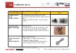
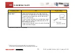
Installation tool 2

Name (temporary)

Use

Image

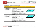
Protection cover for the 
corner of display 
(UKOG1008MPZZ)

- Reduce shock while moving and installing

These covers are attached on the two bottom corners 

of PN-V601 to protect PN-V601 from shock.

It is easy to remove the cover. It is not required 

for installation.

- 2 units of this cover are necessary per one PN-V601. 

We will provide following service parts for installation (they are subject to fees)

* if you need above tools, please contact delivery agent or our sales reps.

Summary of Contents for PN-V601

Page 1: ...CONFIDENTIAL Rev1 4 2010 09 30 Business Solutions Equipment Division Business Solutions Dept SHARP Corporation PN V601 Installation Guidelines ...

Page 2: ...ssions on this document are subject to change without notice Procedures of installation Overall precautions Precautions for temperature and clearance space 1 2 3 4 5 Precautions for sunlight exposure Precautions against dust Position of exhaust fan and intake port Precautions for dew condensation water drops and salt damage Precautions for orientation power supply and voltage Precautions for vibra...

Page 3: ...s for workers Attachment precaution 2 How to temporarily store the display after taking it from the box We recommend temporarily storing the display on a temporary stand If you inevitably put the surface of LCD monitor on the ground when there is no temporary stand check whether there is dust and or projection and place on a clean board larger than the display How to check and or store the accesso...

Page 4: ...t and Stand Unlike Sharp PN E standard models the PN V601 requires close attention for handling due to its thin bezel Even the dealers or worker familiar with the conventional models must confirm precautions beforehand Please study the installation of the Sharp recommended stand as much as possible and please entrust the installation work to Sharp sales subsidiaries or dealers contractors trained ...

Page 5: ...pment etc We will not take any responsibility for any failure damage loss etc which arise from particular installation high ceiling mounting etc and or installation by non Sharp related parties Prior to the installation please examine the potential problems by the installation location and installation method and only operate within the appropriate environment In case of product failure regardless...

Page 6: ...n If the heat gets trapped inside the display the temperature will rise Hence the brightness of back light will be lowered and the screen will be darkened Moreover if the temperature gets too high the power of LCD display will be turned off and the display will be set to the standby mode The thermal influence The heat impact on LCD surface The effect of high temperature Monitors will break down or...

Page 7: ...arance space at the back side surrounding temperature must be carefully controlled Temperature of LCD surface Under 60 degree C Please follow these requirements when setting multi display Refer to the measures and install the display according to its requirements Same with peripheral devices please follow the specifications Securing space at the Top Bottom Left Right Behind Surface of display is n...

Page 8: ... pre mature fan failure 3 5cm or more 10cm or more 20cm or more 30cm or more 40cm or more 50cm or more 60cm or more 70cm or more Auto Variable default setting 30 5 32 32 5 36 38 Setting 1 Rotation speed 50 29 30 30 30 5 30 5 31 32 33 3 5cm or more 10cm or more 20cm or more 30cm or more 40cm or more 50cm or more 60cm or more 70cm or more Auto Variable default setting 30 31 31 5 34 Setting 1 Rotatio...

Page 9: ...rged The warranty does not include pre mature fan failure 3 5cm or more 10cm or more 20cm or more 30cm or more 40cm or more Auto Variable default setting 33 26 38 39 40 3 5cm or more 10cm or more 20cm or more 30cm or more 40cm or more 50cm or more 60cm or more Auto Variable default setting 24 5 30 5 33 35 37 5 39 40 For case of 3 x 3 multi screen displays Unit degree celsius Fan rotation speed Set...

Page 10: ... 5X5 multi display Temperature under operation VS Clearance space Temperature Clearance space Precautions for temperature and clearance space 4 20 0 25 0 30 0 35 0 40 0 3 5cm 10cm 20cm 30cm 40cm 50cm 60cm 70cm Life time of fan 5 years Setting Automatic Life time of fan 5 years Setting Setting 1 Life time of fan 2 5 years Setting Automatic 20 0 25 0 30 0 35 0 40 0 3 5cm 10cm 20cm 30cm 40cm 50cm 60c...

Page 11: ...ontrol the surrounding temperature around 0 degree C to 40 degree C Adding a cooling fan Improve the ventilation by widening its space Using an air conditioner or fan Lowering the brightness of display The effectiveness of each measure differs depending on the environment Please choose the best measure for respective environment Countermeasure for lack of clearance space Example of fan installatio...

Page 12: ...as especially when using in an outdoor or semi outdoor environment Set a sun shade above the monitor Utilize the shade of the building Place the monitor where there is no direct sunlight Change the direction of the monitor to avoid sunlight Using some object which can block out the direct sunlight You should pay attention to strong winds like hurricanes The effect of direct sunlight If the product...

Page 13: ...undamentally LCD monitor is designed for indoor usage When it is being used outdoor or at dusty places such as railway station or close to the traffic the solutions against dust must be considered If the anti dust solutions are not being considered The dust will enter into the LCD panel through the gaps and will cause the distorted image see example below and will break down in the end In general ...

Page 14: ...rmly with screws 1180 754 2 232 Cover removal Intake port of cooling fan Do NOT cover this area Do NOT cover vent hole and intake port If the temperature of the inside of the monitor is rising it may cause the failure of the monitor Do NOT cover engine grille Do NOT cover this area for replacing of cooling fan Position of exhaust fan and intake port 13 ...

Page 15: ...near the sea or lakes where there is high humidity The environment which has high possibility of liquid drops Semi outdoor place where strong winded rain typhoon could potentially reach the monitor The place which is below the pipes inside the ceiling When the pipes have leaking problems there is a possibility for water drops to enter the monitor through the vents When installing in these places c...

Page 16: ...tween 0 to 20 degrees downward Even within 20 degrees range please consult individually when installing with inclination Please consult for facing up installation PN V601 is designed to be used under commercial 100V 240V power supply When aligning multiple screens shortage of power supply may occur Consideration should be taken to collect several circuits and supply power evenly Avoid over power c...

Page 17: ...les If the monitors will be used in the place which has the possibility of even small vibration like railway station s platform shock absorber must be considered When a still image is being displayed for a long period image retention might occur Image retention can be removed by displaying motion images or turning off the monitor However the longer the still image is being displayed the harder to ...

Page 18: ...ontext we strongly recommend the operation check before installation When using interface expansion board PN ZB02 confirm its input output signal Please confirm if the installation tools e g bezel sheet are set correctly before installation 1 Press the SIZE key over 5 sec and F is displayed at the upper left of screen 2 Press in turn the keys 3 The screen display changes in following sequence with...

Page 19: ...side outer dimension 1335 9 mm short side outer dimension 754 2 mm long side short side tolerance is 2 0 mm 0 5 mm table on the right Considering display allowance 2 0 mm 0 5 mm please leave space beforehand for adjustment when installing Planned outer dimension mm Outer tolerance mm Long side 1335 9 2 0 0 5 Short side 754 2 2 0 0 5 Weight PN V601 approx 44kg PN ZB02 approx 0 5kg ...

Page 20: ... LCD panel by heat expansion it may cause a white spot Spacing installation device Precautions for space between displays Considering thermal expansion please reserve enough space when installing Requirement for minimum space can be calculated as follows Space for long side length Maximum surrounding temperature under operation surrounding temperature when installed 20 x 0 016 mm or more Space for...

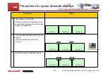
Page 21: ...lays at the bottom has not been completed yet 2 Insert spacing installation device into the displays Align the position and then fix the monitors 3 Extract the spacing installation device PN V601 1 PN V601 2 PN V601 3 20 PN V601 1 PN V601 2 PN V601 3 PN V601 1 PN V601 2 PN V601 3 Spacing installation device Precautions for space between displays How to use spacing installation device 1 ...

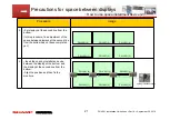
Page 22: ... the bottom has not been completed yet 5 Insert the spacing installation device between the display at the bottom and the display at the second line from the bottom Align the position and then fix the monitors 21 PN V601 4 PN V601 5 PN V601 6 PN V601 1 PN V601 2 PN V601 3 PN V601 4 PN V601 5 PN V601 6 PN V601 1 PN V601 2 PN V601 3 Spacing installation device Precautions for space between displays ...

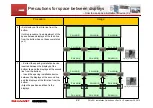
Page 23: ...bottom line and the displays at the second line from the bottom Insert the spacing installation device between the displays at the second line and the displays at the third line from the bottom Align the position and then fix the displays 22 PN V601 4 PN V601 5 PN V601 6 PN V601 1 PN V601 2 PN V601 3 PN V601 7 PN V601 8 PN V601 9 PN V601 4 PN V601 5 PN V601 6 PN V601 1 PN V601 2 PN V601 3 PN V601 ...

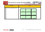
Page 24: ...ptember 30 2010 CONFIDENTIAL Procedure Image 8 Extract the spacing installation device 23 PN V601 4 PN V601 5 PN V601 6 PN V601 1 PN V601 2 PN V601 3 PN V601 7 PN V601 8 PN V601 9 Precautions for space between displays How to use space installment device 4 ...

Page 25: ...placing fan cover is possible Precautions on stand installation Concern about surrounding spaces LCD surface Secure at least 20cm Installation example for stand installation Secure Clearance space for the rear Wall Concern about securing stand For safety please give measures for preventing fall of monitors in case of earthquake etc Secure firmly displays with wire or anchor etc Securing space at u...

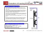
Page 26: ...l there is a possibility that heat will rise because upper displays absorb the exhausting heat from lower displays Please refer to Precautions for temperature and clearance space P3 P7 to study details Please use the mounting bracket which can support 4 times weight of a display It is necessary that the wall on which displays are mounted must support 4 times total weight of displays and mounting b...

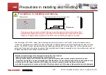
Page 27: ...oving Please don t handle any other part of the display The PN V601 is high density product so that please pay attention NOT to let the edge of PV V601 support the entire weight load Please take extra caution to make sure that weight load each display is supported only by the mounting system and not a neighboring display when building a multi screen wall Method of interim storage of the display af...

Page 28: ...isplay Please support the display symmetrically by gripping both handles or both corners of the display in order to distribute the pressure equally on the display Apply the pressure symmetrically to the display which is standing vertically with handle installation tools etc Bigger board than the display Protection sheet like blanket PN V601 Please grip both handles when the display is laid on the ...

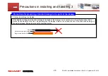
Page 29: ...3 1 Please do not drag the display If the display is dragged strain and damage to the parts of the display can be caused even if a protection sheet like a blanket is underneath on the floor Especially when the display is laid on the screen the risk of the strain and damage of the parts increase Please be sure not to drag the display Bigger board than PN V601 Protection sheets like blanket PN V601 ...

Page 30: ...5mm hole diameter Oversize of hole diameter can cause unfastening of the captive nut by the mounting screw 4 Please use screws being correct length written in operation material of display Over length of screw can cause unfastening of the captive nut by the mounting screw 5 Please take measures by all means to prevent the screws loosening For example using screws with washer 6 Please tighten screw...

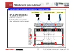
Page 31: ...n Installation handle Installation eyebolt device Interlocking pipe Please take care not to add pressure to parts other than the ones marked with a heavy line in the diagram during installation and maintenance If pressure is added to other parts the display itself may be distorted or damaged Attachment precaution 2 Support PN V601 by holding both corners ...

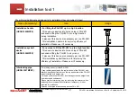
Page 32: ...1 up by crane 2 pieces of this device are necessary per one PN V601 This installation eyebolt device is for improving the efficiency of installation Please use it if necessary Interlocking pipe UKOG 1007MPZZ For making it easy to install PN V601 It can reduce gap between the top to bottom of the PN V601 and interlock each panel from both on the top and bottom of the PN V601 when installing with a ...

Page 33: ...ock while moving and installing These covers are attached on the two bottom corners of PN V601 to protect PN V601 from shock It is easy to remove the cover It is not required for installation 2 units of this cover are necessary per one PN V601 We will provide following service parts for installation they are subject to fees if you need above tools please contact delivery agent or our sales reps ...

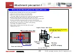
Page 34: ...Please take care that the sheet does not extend out of display side Protection spacer for Portrait UKOG1010MPZZ Protection of display Insert this spacer between the PN V601 while installing neighboring PN V601 s thickness 0 5 mm This tool is used to avoid damage of the bezel at the installation and the position adjustment of the display This is not a required tool Please take care that the sheet d...

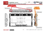
Page 35: ...he LCD side is the front LCD side Rear side Installation tool 4 Pasting position of Protecting spacer 2 positions of protecting spacer for vertical bezels On the second screw from the right on the back row The LCD side is the front On the second screw from the top on the back row The LCD side is the front On the second screw from the bottom on the back row The LCD side is the front LCD side ...

Page 36: ...Z Temporary stand This stand is for fixing PN V601 temporarily to check operation and perform settings before installation 2 pieces of this stand are necessary per one PN V601 Supply cable for 200 volts QACCJA104WJPZ Supply cable for 200 volts Supply cable for 100 120V volts is enclosed in PN V601 for Japan US model If PN V601 is used with with 200 volt environment power supply cable for 200 volts...

Page 37: ...ch bezel sheets on the 4 sides of the PN V601 to cover the white areas on the sides of the display 4 bezel sheets is necessary per one PN V601 for top bottom right left side In order to study the detail on how to attach bezel sheet please refer to the introduction material enclosed in PN V601 package one sheet Please note that this sheet can not be put on after setting up the multi screen display ...

Page 38: ...the same space Based on the temperature actually measured please estimate the temperature of each part during the condition that the room temperature is highest and take necessary countermeasures against heat For instance it is effective to install a ventilation fan to reduce the chance of overheating We will recommend you to select a wireless mouse and keyboard to assist with PC operation Precaut...

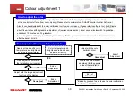
Page 39: ...n and about 10 minutes with 32 gradation As the brightness of display is not steady immediately after the power on please adjust color 60 minutes or more after the backlight is lit How to adjust the color Color Adjustment Procedures for New Installation Need set to a specific color temperature and brightness by using the colorimeter YES Need adjust the color with the installation environment NO Co...

Page 40: ...displays due to change over time Adjust the replaced display to the targeted color and the brightness with the color calibration tool End of Adjustment for One unit End of Adjustment End of Adjustment End of Adjustment End of Adjustment End of Adjustment Can adjust Can adjust Can adjust Can adjust all Can adjust Select a display and measure targeted color and brightness with the color calibration ...

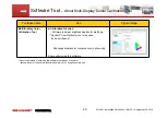
Page 41: ...tware to adjust brightness and color matching Spyder3 from Datacolor Inc is required to be purchased http spyder datacolor com product mc s3pro php Sharp will provide this software Software Tool About Multi Display Colour Calibration Tool About the method of obtaining this software tool please consult our sales window or the dealers resellers from which you bought the main unit ...

Page 42: ...ware Control PN V601 from PC Can turn power on and off change input signal change settings etc Can control multiple displays Can limit the operation by setting the user level Can monitor display condition if by any chance Sharp will provide this software About the method of obtaining this software tool please consult our sales window or the dealers resellers from which you bought the main unit ...

Page 43: ...a LAN network Network version PN SS02 is installed on the server PC while the Viewer version PN SV01 is installed on the client PCs Professional version PN SP02 Marketed in Japan only Enhanced version of the PN SS02 network version Functions of the contents delivery and management etc are strengthened and clients up to 1 000 are supported Even complex operation in the large system can be easily us...

Page 44: ...wipe with a damp or dusty cloth in order to protect the LCD Maintenance Checking Items Maintenance Checking Items 1 Daily maintenance 1 1 Cleaning of LCD surface 1 2 Monitoring operating conditions 2 Periodical maintenance 2 1 Checking the installation conditions Checking the mounting bracket for the main units for loose mounting bolts and screws etc 2 2 Cleaning of port of intake fan and its surr...

Page 45: ...net Dust adheres to the intake holes Please remove dust in this part 2 Dust adheres to the inside of the fan cover Please detach fan cover and remove the dust that attaches internally 3 Dust might adhere to the fan blades In this case please clean the fan by detaching it if necessary Cleaning Cycle It varies according to the environment In a busy area cleaning might become necessary more often Ple...

Page 46: ...ement parts please consult the dealers resellers that sold the main unit or the sales contact of our company Replacement of Fan In addition to the periodical maintenance we would like you to study Maintenance contract with Sharp sales subsidiaries or dealers contractors trained by Sharp About this please consult the shop that sold the main unit or the sales contact of our company ...

Page 47: ...46 ...
Reviews: