


34
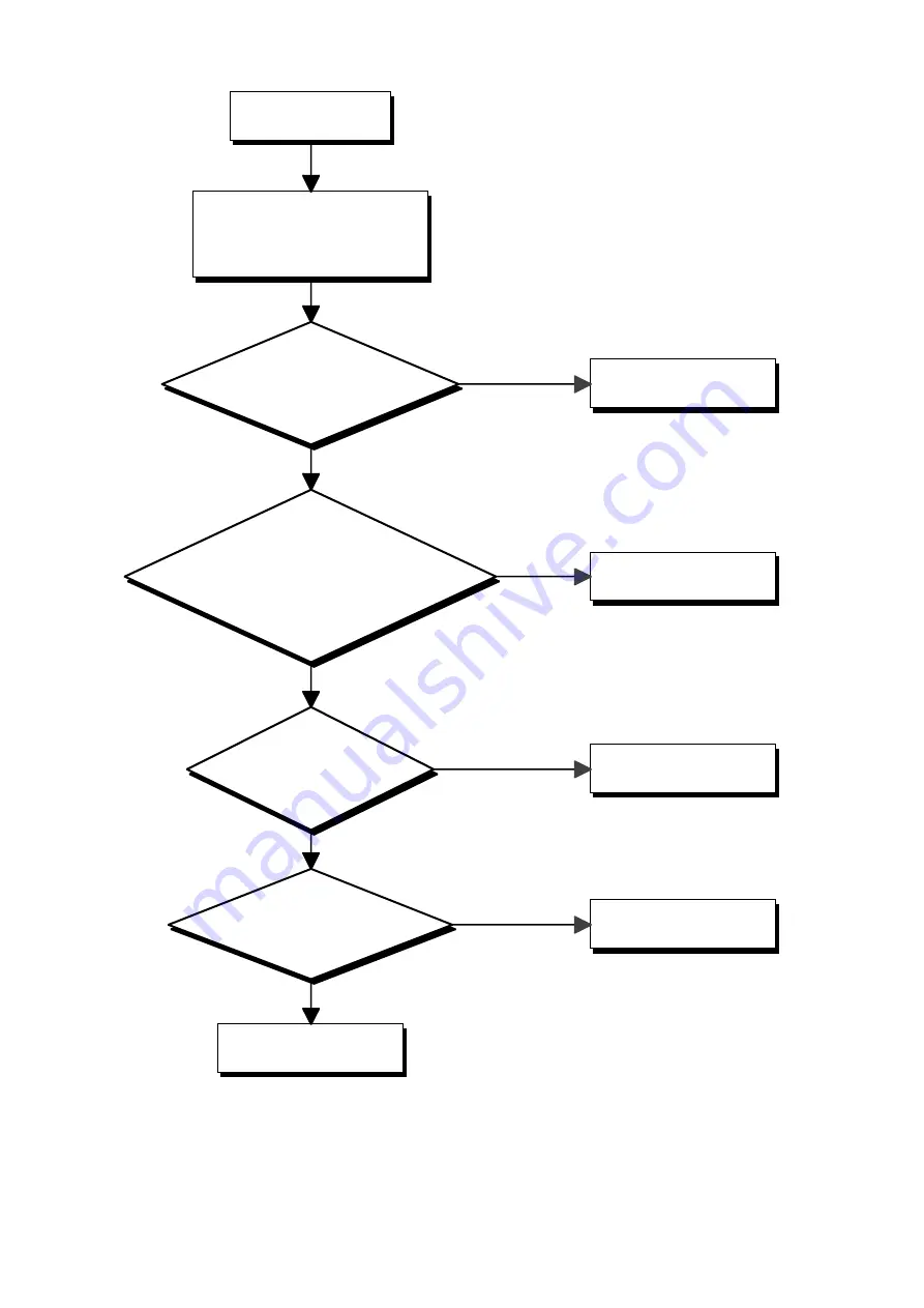
Audio Circuit Check
Input a 500mV(RMS) sine-wave to
audio input terminal.
Set the volume to maximize and
mute off.
Is the signal outputted from
IC500-pin7?
Are the signals outputted from IC507-
pin2 and IC508-pin2?
Does the signals change 0V when mute
off?
Is the signal inputted to
IC503-pin5?
Is 2.85V(RMS) sine-wave
outputted from TP504?
Check speaker.
IC500 failure
IC507,508 failure.
IC503 failure.
IC503 failure.
Yes
Yes
Yes
Yes
No
No
No
No
Summary of Contents for QD-101MM
Page 39: ...38 6 CIRCUIT DIAGRAM PWB Fig 27 CIRCUIT DIAGRAM MAIN CIRCUIT No 1 ...
Page 40: ...39 Fig 27 CIRCUIT DIAGRAM MAIN CIRCUIT No 1 ...
Page 41: ...40 Fig 28 CIRCUIT DIAGRAM MAIN CIRCUIT No 2 ...
Page 42: ...41 Fig 28 CIRCUIT DIAGRAM MAIN CIRCUIT No 2 ...
Page 43: ...42 Fig 29 CIRCUIT DIAGRAM MAIN CIRCUIT No 3 ...
Page 44: ...43 Fig 29 CIRCUIT DIAGRAM MAIN CIRCUIT No 3 ...
Page 45: ...44 Fig 30 CIRCUIT DIAGRAM MAIN CIRCUIT No 4 ...
Page 46: ...45 Fig 30 CIRCUIT DIAGRAM MAIN CIRCUIT No 4 ...
Page 47: ...46 Fig 31 CIRCUIT DIAGRAM POWER CIRCUIT ...
Page 48: ...47 Fig 31 CIRCUIT DIAGRAM POWER CIRCUIT ...
Page 49: ...48 Fig 32 CIRCUIT DIAGRAM VIDEO CIRCUIT ...
Page 50: ...49 Fig 32 CIRCUIT DIAGRAM VIDEO CIRCUIT ...
Page 51: ...50 Fig 33 CIRCUIT DIAGRAM AUDIO CIRCUIT ...
Page 52: ...51 Fig 33 CIRCUIT DIAGRAM AUDIO CIRCUIT ...
Page 53: ...52 Fig 34 PWB PATTERN MAIN PWB FRONT SIDE ...
Page 54: ...53 Fig 34 PWB PATTERN MAIN PWB REAR SIDE ...
Page 66: ...PRINTED IN GERMANY ...


