R-7500AT
13
●
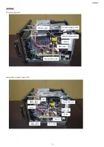
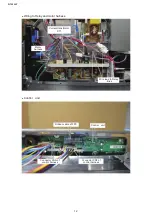
Wiring to Relay and motor harness
●
Control
unit
Current transformer
CT1
Motor
harness
Wire lead to Relay
:
Blue
Ribbon cable of FPC
Control
unit
Connector CNF
of
control harness
Connector CNG
of
control harness
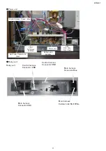
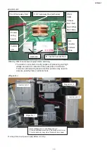
●Inverter unit
FA:
HV
w
ire
assy
R
e
d
F:
HV
w
ire
assy
R
e
d
(w
it
h
cas
e
)
CN-A:
PWM
ha
rne
ss
No.1:
R
e
d
No.2:
Wh
ite
No.3:
Bl
ue
AC:
Inverter
ha
rne
ss
Bl
ue
M:
Inverter
ha
rne
ss
R
e
d
Inverter
unit
H
e
a
t
s
in
k
P
rinte
d
w
irin
g
boa
r
d
Warning: Disconnect power supply before servicing.
The inverter unit contain circuitry capable of producing very high
voltage and current, contact with the heat sinks, FA terminal,
F terminal, printed wiring board and other portions may result in
a severe, possibly fatal, electrical shock.
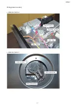
Magnetron -2
Inverter unit -1
Inverter unit -2
Magnetron -1
Both of Magnetron-1 and Magnetron-2
FA terminal(back plate side): Red(with white case)
F terminal(cavity assy side): Red(with blue case)
Warning: Disconnect power supply before servicing.
●
Magnetron

