4
R-7500AT
PRECAUTIONS FOR USING LEAD-FREE SOLDER
Employing lead-free solder
The "Main PWB" of this model employs lead-free solder. This is indicated by the "LF" symbol printed on the PWB and in the service
manual. The suffix letter indicates the alloy type of the solder.
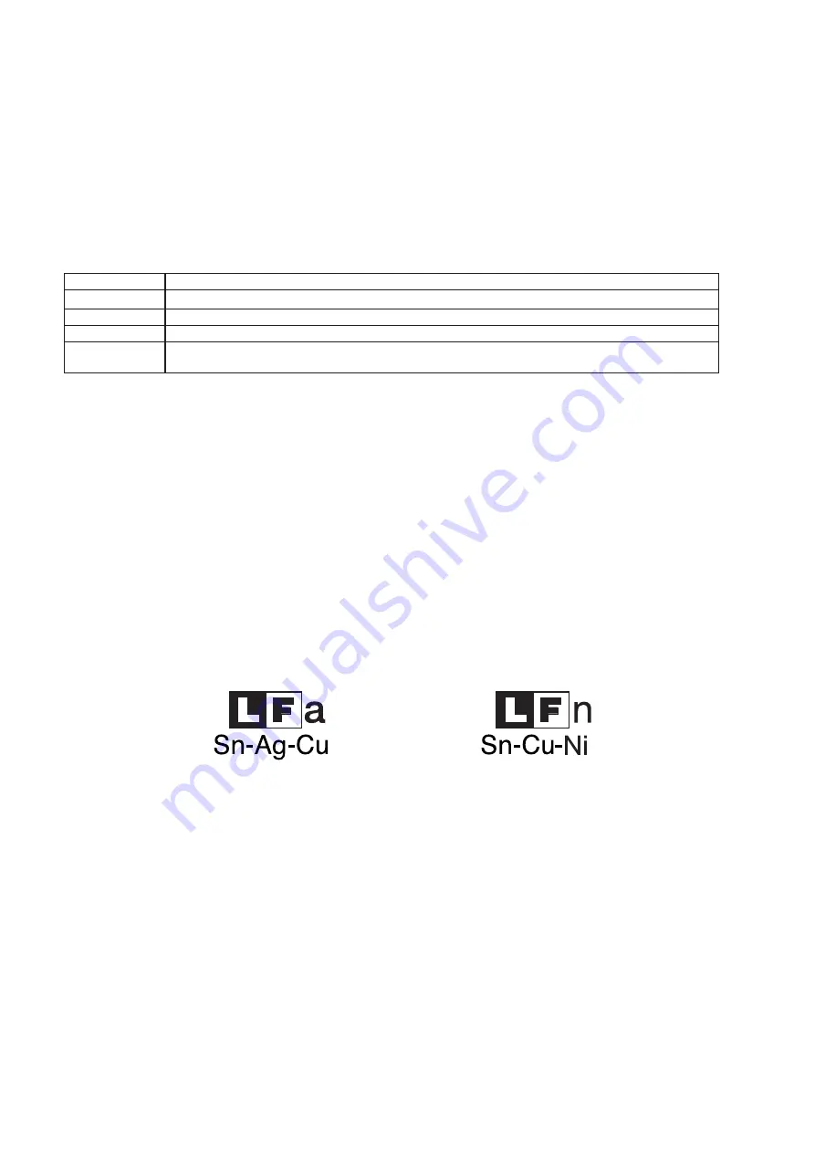
Example:
Indicates lead-free solder of tin, silver and copper
Indicates lead-free solder of tin, copper and nickel
Using lead-free wire solder
When repairing a PWB with the "LF" symbol, only lead-free solder should be used. (Using normal tin/lead alloy solder may result in
cold soldered joints and damage to printed patterns.)
As the melting point of lead-free solder is approximately 40ºC higher than tin/lead alloy solder, it is recommend that a dedicated bit is
used, and that the iron temperature is adjusted accordingly.
Soldering
As the melting point of lead-free solder (Sn-Ag-Cu, Sn-Cu-Ni) is higher and has poorer wettability, (flow), to prevent damage to the
land of the PWB, extreme care should be taken not to leave the bit in contact with the PWB for an extended period of time. Remove
the bit as soon as a good flow is achieved. The high content of tin in lead free solder will cause premature corrosion of the bit. To re
-
duce wear on the bit, reduce the temperature or turn off the iron when it is not required.
Leaving different types of solder on the bit will cause contamination of the different alloys, which will alter their characteristics, mak
-
ing good soldering more difficult. It will be necessary to clean and replace bits more often when using lead-free solder. To reduce bit
wear, care should be taken to clean the bit thoroughly after each use.
Oven should not be run empty. To test for the presence of microwave energy within a cavity, place a cup of cold water on the ceram -
ic oven floor, close the door and set the power to 100% and set the microwave timer for one (1) minute. When the one minute has
elapsed (timer at zero) carefully check that the water is now hot. If the water remains cold carry out Before Servicing procedure and
re -examine the connections to the component being tested.
When all service work is completed and the oven is fully assembled, the microwave power output should be checked and microwave
leakage test should be carried out.
BEFORE REPLACING THE PRINTED WIRING BOARD
Some normal boards are found in board units that have been returned due to oven failure. So, most of board replacements may arise
from poor harness connection. Accordingly, before replacing any board that was judged to require its replacement, use the following
procedure to re-check that the connection terminal of a connector has been properly inserted:
1. When the connectors have been incorrectly inserted to the control unit.
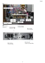
CONNECTOR
Symptom
CN -A
The oven can not be powered on.Antenna motor(s) does not run.Blower motor(s) does not run.
CN -B
The oven can not be powered on.No heating can be done.LED light does not illuminate.
CN -D,CN -F
No indication, no key insertion and no buzzer sound.
CN -G
The power level can not be varied.MGT thermistor(s) does not work.Magnetron(s) does not work.ER
-
ROR(s) shows.
2. When latch switch adjustment is incorrect
When latch switch adjustment is incorrect, symptoms such as no heating, no heating start, no activation even with start button
pressed, etc. will occur.

