background image


Noise reduction system manufactured under license from Dolby Labora-

tories Licensing Corporation. “Dolby” and the double-D symbol are trade-
marks of Dolby Laboratories Licensing Corporation.


 von Dolby Laboratories Li-

censing 


 Das Wort “Dolby” 

 das Symbol des

doppelten   sind die Warenzeichen von 

 Laboratories Licensing Cor-

poration.

 de bruits Dolby: Circuit 


 des Dolby Labo-

ratories Licensing Corporation. 

 mot “Dolby” et 


 double 

sont 

 marques 


 Dolby Laboratories 


l

In the interests of user-safety the set should be restored to its ori-

ginal condition and only parts identical to those specified be used.

.


 der 


 dieses 


 auf


 die 


 verwendet 

l

D a n s  

 de la 

 de 


 devra 

 dans 

 condition premiere et 

 des pieces 

q u e s    


SPECIFICATIONS . . . . . . . . . . . . . . . . . . . . . . . . . . . . . . . . . . . . . . . . . .

NAMES OF PARTS . . . . . . . . . . . . . . . . . . . . . . . . . . . . . . . . . . . . . . . . . . . . .

Page

WIRING SIDE OF 

 . . . . . . . . . . . . . . 

 13, 14

SCHEMATIC DIAGRAM . . . . . . . . . . . . . . . . . . . . . . . . . . . . . . . . . . . . 15. 16

DISASSEMBLY.. ..................................................

5, 6

EQUIVALENT CIRCUIT (BLOCK

BLOCK DIAGRAM ...................................................

7

DIAGRAM) OF

...............................................

17

CIRCUIT ADJUSTMENT.. ..................................... 8, 9

TYPES OF TRANSISTOR AND LED.. ........................ 17

MECHANICAL ADJUSTMENT ...........................

11

EXPLODED VIEW ............................................

18, 19

NOTES ON SCHEMATIC DIAGRAM.. ....................... 12

REPLACEMENT PARTS LIST.. ..........................

Seite

Seite

DATEN . . . . . . . . . . . . . . . . . . . . . . . . . . . . . . . . . . . . . . . . . . 2 - 4

SCHALTPLAN . . . . . . . . . . . . . . . . . . . . . . .

15, 16

DER

 . . . . . . . . . . . . . . . . . . . . . . . . . . . . . . . . . . . 2 - 4


........................................................

5, 6

 DES 

BLOCKSCHALTPLAN ...............................................

7

..............................................

17

................................ 8, 9


..........................

11

.................................................

17

ANMERKUNGEN 

........................... 18, 19

 SCHALTPLAN ......................... 12

ERSATZTEILLISTE ..........................................

 DER

...........................................

13, 14


Page

..........................................

2 - 4

NOMENCLATURE.. .............................................

2 - 4

....................................................

5, 6

.................................... 7

 DU CIRCUIT.. ....................................... 8, 9
 DE

.............................

REMARQUES CONCERNANT LE


............................ 12


 DE LA PLAQUETTE

Page

DE MONTAGE

.............................. 13, 14


........................... 15, 16

CIRCUITS EQUIVALENTS 

DE Cl.. .........................................

17

TYPES DE TRANSISTOR ET LED.. ...........................

  E N  

.............................................

18, 19

 DES 

 DE RECHANGE ...................


Summary of Contents for RT-W500H

Page 1: ...celles specifiees doivent dtre utilisees A INF E I ONTENTS v 9 i CJ I SPECIFICATIONS NAMES OF PARTS L 4 Page WIRING SIDE OF P W BOARD _ 13 14 SCHEMATIC DIAGRAM 15 16 DISASSEMBLY 5 6 EQUIVALENT CIRCUIT BLOCK BLOCK DIAGRAM 7 DIAGRAM OF IC 17 CIRCUIT ADJUSTMENT 8 9 TYPES OF TRANSISTOR AND LED 17 MECHANICAL ADJUSTMENT 10 11 EXPLODED VIEW 18 19 NOTES ON SCHEMATIC DIAGRAM 12 REPLACEMENT PARTS LIST 20 24...

Page 2: ...ms Line Out 5 5 0 mV 0 dBI 50 kohms DIN Out 5 5 0 mV 0 dB 50 koms Specifications for this model are subject to change without prior notice 1 Headphones Jack 2 Deck 2 Digital Tape Counter and Reset Button j 1 1 8 4 q NAMES OF PARTS I I I 3 Deck 2 Cassette Compartment I I I I I I 4 Deck 1 l Cassette Compartment 5 Record Level Balance Control 6 Sharpscan Peak Level Display 7 Record Level Control 8 De...

Page 3: ...pegel und Belastungsimpedanz Kopfhlirerausgang 0 2 mW 0 dB 8 Ohm Direktausgang 550 mV 0 dBI 50 kOhm DIN Ausgang 550 mV 0 dB 50 kOhm Die technischen Daten fur dieses Model1 kijnnen ohne vor herige Ankiindigung Anderungen unterworfen sein BEZEICHNUNG DER TEILE 1 Kopfhorerbuchse 2 Deck 2 Digitales Bandzahlwerk und Rtickstelltaste 3 Deck 2 Cassettenfach 4 Deck I Cassettenfach 5 Aufnahmepegel Balancest...

Page 4: ...s du demontage de I appareil Apr la rkpara tion de I appareil s assurer de redisposer les fils tel qu ils Btaient avant le dbmontage 4 Faire attention I Blectricit6 statique des circuits integr s et des autres circuits lors de la rkparation SCH RITT 1 2 Frontolatte 3 Laufwerkblock 4 LED leiterplatte 1 I Schraube lH x2 1 5 6 7 ENTFERNEN V E R F A H R E N ABBIL DUNG Gehluse 1 Schraube A xE I Schraub...

Page 5: ...servicing ZTEP REMOVAL PROCEDURE FIGURE 1 C a b i n e t 1 Screw lA1x5 5 l 2 Front Panel 1 Screw IB x7 2 Lead C xl 3 Socket D x3 4 Record playback selector rod E xl 3 Mechanism Block I Screw F x6 2 Tape counter drive belt G xl 4 LED P W B 1 Screw H xZ 5 Record Level Con 1 Screw 11x3 trol P W B and 2 Bracket J xl Record Level 3 Knob K xl Balance Control P W B 7 5 2 6 Headphones Jack 1 Screw L xl 5 3...

Page 6: ...acteristiques de ce modele sont sujettes a modifica tion sans preavis NOMENCLATURE 1 Douille de casque 2 Platine 2 Compteur numerique de bande et bouton de remise a zero 3 Platine 2 Compartiment de cassette 4 Platine 1 Compartiment de cassette 5 Commande de balance de niveau d enregistrement 6 Afficharge de niveau de c e Sharpscan 7 Commande de niveau d enregistrement 8 Platine 2 Bouton d enregist...

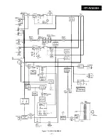
Page 7: ... s t I ll Figure 7 BLOCK DIAGRAM ...

Page 8: ...6 0 ch Figure 8 3 BIAS CURRENT Electronic ERASE CURRENT Metal 36 _ 4 V Normal 540 mV DECK 1 PLAYBACK SENSITIVITY DECK 2 PLAYBACK SENSITIVITY See that the electronic voltmeter reading is within the range from 481 mV to 606 mV If not take the proce dures shown in the Table l 1 RECORD PLAYBACK SENSITIVITY 1 Adjust the record level knobs so that the electronic volt meter reads 380 mV 2 Playback the no...

Page 9: ...4 Testband vlTT 150 WIEDERGABE EMPFINDLICH KEIT VON DECK 1 ENSlBlLlTi DE ECTURE DE LI LATINE 1 3ande d essai VITT 150 VR104 VR204 Vormal 540 mV WIEDERGABE EMPFINDLICH KEIT VON DECK 2 Testband VITT 150 oberpriifen ob der elektronische Spannungsmesser 481 mV bis 606 mV anzeigt Wenn es nicht so ist die Nachsteilung gem Tabelle 1 vornehmen 1 Den Aufnahmepe gelsteller so einstel len da5 der elektronisc...

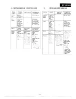
Page 10: ... rape speed Test tape High speed MTT 111 Normal speed MTT 111 High speed Deck 1 6 000 T k Deck 2 6 000 2Ok 40 Normal speed Deck 1 3 000 I t Deck 2 3 000 ilOk 20 l Perform the high speed adjustment first and then the normal speed ad justment iigh speed Ieck 1 VR401 Ieck 2 VR40 dormal speed leek 1 VR40 leek 2 VR40L Short TPI an ground when performing tt high speed as justment Figure 10 2 AZIMUTH WAV...

Page 11: ...urzschlief3en 3000 Hz l Zuerst die hohe dann die norma le Geschwindig keit einstellen ARTICLE uissance l entrai iement ouole Azimuth Jitesse de a bande RiGLAGE MECANIQUE GABARIT Cassette de mesure de tension de la bande TW 2412 Compteur de couple Lecture TW 2111 Avance rapide TW 2231 Rebobinage TW 2231 Bande d essai MTT 114 Bande d essai Grande Vitesse MTT 111 Vitesse normale MTT 111 POINTS DE Rtk...

Page 12: ...larkondensator P P Polypropylentyp l Die in den einzelnen Teilen angegebenen Spannungen wer den mit einem DigitalvielfachmeRgerbt zwischen dem be treffen den Teil und dem Chassis ohne Signalzuleitung gemessen l Anderungen des schematischen Schaltplans und der Ver drahtungsseite der Leiterplatte fiir dieses Model1 im Sinne von Verbesserungen jederzeit vorbehalten Die mit B 2L Z bezeichneten Teile s...

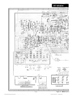
Page 13: ...1 2 3 I 4 5 6 ylu 0 j g RIO r II rl I i L d r I R e I L L L _ 2 J RECORD LEVEL CONTROL PWB A4 0610 0609 0606 L E D PWB A2 1 2 3 4 5 6 13 Figure 13 WIRING SIDE 0 ...

Page 14: ...7 8 9 I 1 0 11 1 2 7 1 I 3 CNS 5 T POWER TRANSFORMER IPWB A6 1 I iMAIN P W B A I 1 I I 7 RED r 1G SIDE OF P W BOARD 14 ...

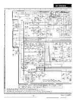
Page 15: ...1214 C BIAS OSC 0401 9402 2SA4933 SR DUBBING SPEED CONTROL e l NOTES ON SCHEMATIC DIAGRAM can be found on page 12 l ANMERKUNGEN ZUM SCHEMATISCHEN SCHALTPLAN stehen auf Seite 12 l REMARQUES CONCERNANT LE DIAGRAMME SCHEMATIQUE sont indiqukes la page 12 1 2 3 I 4 5 I 6 15 Figure 15 sCHEMATI I _ ___ _ __ ...

Page 16: ...7 I 8 9 10 I 11 I 12 mWa bJlFO 2SCl740 SR MPX 0 1 0 4 2sc1740 SR IMAIN PWB AI I DOLBY ON OFF CONTROL r I XC1740 SR I EVEL METER r1 POWER SW 1 7 I 8 9 10 11 12 SCHEMATIC DIAGRAM 1 6 ...

Page 17: ...A OUTu 0 T u OUTS OUTzn OUT 4 ICHII O U T GND N w AMP OUTss 0UT m OUT36 OUTze OUT 8 ICHZI OUTS IN8 Figure 17 l EQUIVALENT CIRCUIT BLOCK DIAGRAM OF IC 2sc1740 SR 2SA933 SR 2SC1214 C SLH 56MCF Green SLH 56VCF Red 2X2878 0 D 000 F ml ilid snO E C B 0 000 E C B Figure 17 2 TY PES OF TRANSISTOR AND LED 17 _ _ ...

Page 18: ...1 I 2 I 3 I 4 I i I c 7 6 A 6 7 66 2 9 8 7 yv q35 I j 3 SW10 14 3 2 D 2 J I LJ 7 19 I 18 I I9 E 8d B C I63 F G 72 IL Ii M I II A B C D E F G h H ...

Page 19: ...1 I 2 I 3 4 5 I 6 2 2 5 x 2 ii 611 1 I 2 3 I 4 5 I 6 Figure 19 CABINET EXPLODED VIEW 19 ...

Page 20: ...SC2878 B O 2 03 VS2SC1740SR 1 Silicon NPN 2SC1740 SR 0205 VS2SC2878B 1 Silicon NPN 2SC2878 B 0206 211 VS2SC1740SR 1 Silicon NPN 2SC1740 SR a212 VS2SC2878B 1 Silicon NPN 2502878 B Q301 302 VS2SC1214 C 1 Silicon NPN 2SC1214 C 0401 402 VS2SA933SR 1 Silicon PNP 2SA933 SR 0403 405 VS2SC1740SR 1 Silicon NPN 2SC1740 SR A 8 AC AB AC AB AC AB AC A8 AC AB AC AC AB AB DIODES Dl 01 VHDI SS133 1 Silicon 1 SSI ...

Page 21: ...y AF 5 2 94R182910302 Take Up Reel Ass y AF 53 94R18000201 Lever Record Safety AC 5 4 94R18217012 Spring Back Tension AB 55 94R18211259 Bracket Motor AF 56 94R18201306 Rubber Motor AA 57 94R18211202 Screw Caller AA 59 94 RI 8211222 6 0 94Rf 8000507 61 94R18211251 6 2 M LEVP0680AFZZ 6 3 94RlJ200905 6 4 94 R18211050 65 RHEDFOI 02AFZZ 6 6 RHEDHO153AFZZ 67 RHEDAOI 25AFZZ 69 94R18211276 7 0 94 R9076000...

Page 22: ... AA AA AA AA AA AA AA A A A A A A A A A A AA AA A A A A A A A A A A A A AA A A AA A A AA AA AA REF NO R239 R240 R241 R242 R243 R244 R245 R246 R247 R248 R249 R250 R251 R252 R253 R254 R255 R256 R257 R259 R260 R261 R262 R263 R264 R266 R267 R269 R270 R271 R272 R273 R301 302 R303 304 R305 306 4 R307 R308 R309 R310 R311 R401 R402 R404 R405 R407 R408 R409 R411 R412 R413 R414 R415 R503 R504 506 R507 508 R...

Page 23: ...V AA V C T Y P A I EX102J 0 001 pF 2 5 V A A VCTYPAI EX122J 0 0 0 1 2 pF 25V AA VCTYPAl EX332J 0 0 0 3 3 pF 2 5 V A A 21 REF NO c150 151 C l 5 2 Cl 53 C l 5 6 Cl57 c201 c202 C205 C206 c209 c211 C213 C214 C215 C224 C230 C233 C234 C236 C238 c239 C245 C248 c249 C250 251 C252 C253 C256 C257 C301 302 c304 C305 306 c307 c309 c403 1 C501 502 c504 c505 C801 802 Unless othe raise specified resistors are 5 ...

Page 24: ...OI OAFF3 605 LX WZ308OAFZZ 606 XHBSDZOPO4000 608 XHBSD30PO8000 609 XHBSN30FO8000 609 XHBSF30P08000 610 XHBSF40PO8000 610 XHBSN40P08000 611 XHMSF4OPl OK00 613 XHSSD30P08000 6 1 4 XJBSD26P08000 615 XJBSD30P08000 617 XJBSF3OPO8000 618 XJBS33OPlOOOO 619 XJBSDSOPI 0000 620 XWHJZ41 02120 DESCRIPTION CODE Screw with Washer 3 A A x 8mm Screw q58 x 2 7 m m AB S c r e w q53 X IOmm A A Bracket Record Level B...

Reviews: