background image

S H A R P

SERVICE 

 MANUEL DE 

In the interests of 

 the set should be restored to its

original condition and only parts identical to those specified be

used,


 der Benutzer-Sicherheit 

 dieses 

 wieder auf

s e i n e n  


  u n d   n u r   d i e  

schriebenen Teile verwendet 

D a n s  

 de la 

 de 


 devra 

  d a n s   s a   c o n d i t i o n  

  e t  


identiques   


 doivent 


 BK)

(SKC product)

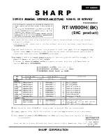
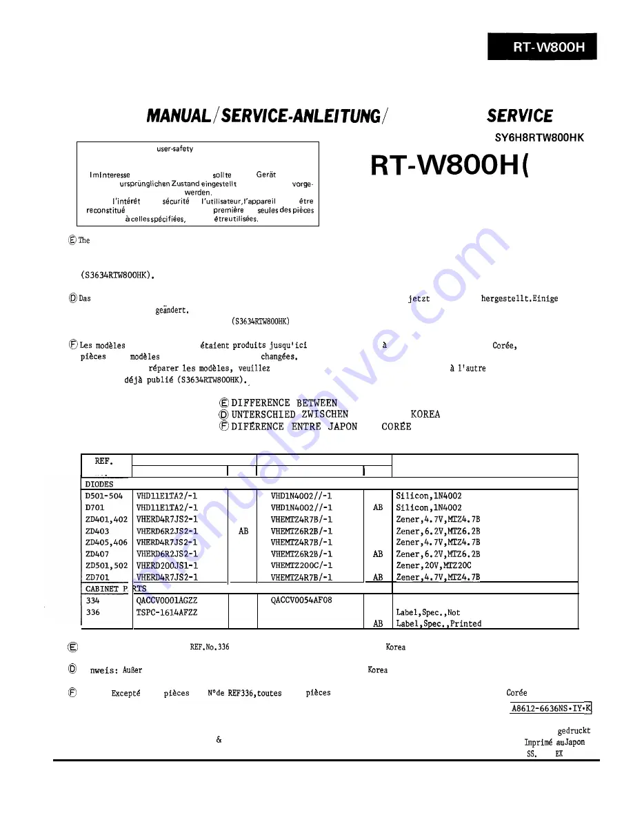
 above model which have so far been produced in Japan is now manufactured in Korea, and their parts

are partially changed.

When servicing them, please refer to this Service Manual and also to the already issued Service Manual

 oben genannte Modell, das bislang in Japan produziert wurde, wird 

 in Korea 

Bauteile wurden 

 Einzelheiten iiber die Wartung sind dieser Service-Anleitung sowie der bereits

erschienenen Service-Anleitung 

 zu entnehmen.


 ci-dessus qui 


 au Japon sont   present produits en 

 et les

 des 

 sont partiellement 

Au moment de 


 se reporter au Manuel de Service et   

 Manuel de

Service 


 JAPAN 

A

N D   K O R E

A


 JAP

A

N UND 


 ET 

MADE 

IN 

JAPAN

MADE 

IN 

KOREA

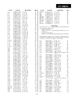
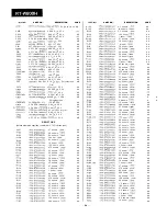
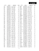
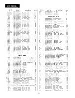
DESCRIPTION

NO.

PART 

NO.

 CODE 

PART NO.

 CODE

AB

AB

AB
AB

AB

AB

AL

AL

AC Power Supply Cord

AB

TSPC-1743AFZZ

AB

 Printed MADE 

IN 

KOREA

TSPC-1744AFZZ

 MADE 

IN 

KOREA

AB

AB

AB

AB

AB

AB

  N o t e :

Except for parts 

 all the parts made in Japan and 

 are interchangeable.

 Hi

 den Teilen (REF Nr.336) sind alle in Japan und 

 hergestellten Teile austauschbar.

 Note: 

 les 

 de 


 les 

 qui sont produites au Japon et en 

 sont

interchangeables.

Printed in Japan

In Japan 

Writer and Editor: Quality   Reliability Control Center of Audio 

Systems 

Group, Sharp Corp. 


SG. 

 SA. 

SHARP CORPORATION

Summary of Contents for RT-W800H

Page 1: ...rge schriebenen Teile verwendet werden l Dans I int de la s6curit6 de I utilisateur I eppareil devra dtre reconstitub dens sa condition premiere et seules des pi es identiques H celles sp6cifi6es doivent 6tre utilis6es CONTENTS Page TYPES OF TRANSISTORS AND LED II 12 SCHEMATIC DIAGRAM 13 14 17 WIRING SIDE OF P W BOARD 15 16 18 EQUIVALENT CIRCUIT BLOCK DIAGRAM O F IC 19 EXPLODED VIEW 20 21 REPLACEM...

Page 2: ...dB 50 kohms Specifications for this model are subject to change without prior notice 1 Deck 1 Cassette Compartment 2 Deck 1 Mode Selector Switch 3 Deck 1 Tape Direction Switch 4 Deck 2 Cassette Compartment 5 Deck 2 Mode Selector Switch 6 Deck 2 Tape Direction Switch 7 Deck 2 Tape Counter and Counter Reset Button 8 Sharpscan Peak Level Display Meters 9 Deck 1 Reverse Button 10 Deck 1 Play Button Il...

Page 3: ...5 0 kOhm DIN Ausgang 5 5 0 mV 0 dB 5 0 kOhm Die technischen Daten fur dieses Model1 ktinnen ohne vor herige AnkijndigungAnderungen unterworfen sein BEZEICHNUNG 1 Deck 1 Cassettenfach 2 Deck 1 Betriebsartenwahlschalter 3 Deck 1 Bandrichtungsschalter 4 Deck 2 Cassettenfach 5 Deck 2 Betriebsartenwahlschalter 6 Deck 2 Bandrichtungsschalter 7 Deck 2 Bandzahlwerk und Zlhlwerkrtickstelltaste 8 Sharpscan ...

Page 4: ... cassette 2 Platine 1 Commutateur de selection de mode 3 Platine 1 Commutateur de sens de defilement de bande 4 Platine 2 Compartiment de cassette 5 Platine 2 Commutateur de selection de mode 6 Platine 2 Commutateur de sens de defilement de bande 7 Platine 2 Compteur de bande et bouton de remise Q zero du compteur 8 Compteurs de niveau de Crete Sharpscan 9 Platine 1 Bouton d inversion 10 Platine 1...

Page 5: ... servicing the unit be sure to rearrange the leads where they were before disassembling 4 Take sufficient care on static electricity of integrated circuits and other circuits when servicing Mechantsm Block Control PWB 2 Screw I x2 A x 2 64 x 8mm 63 x 8mm Black Figure 5 l Figure 5 4 VOLTAGE SELECTION 3x6mm Figure 5 2 Mechanism Block Figure 5 3 K xl Main PWB 63 x 8mm The voltage selector is located ...

Page 6: ... der Spannung notwendig sein sollte benutzen Sie dazu einen Schraubenzieher Drehen Sie den Spannungswahler in beliebiger Richtung bis die gewiinschte Spannungszahl im Fensternneben der Einstell schraube erscheint Pr6cautions pour le d montage Lors du demontage de I appareil et de son remontage suivre les precautions ci dessous pour maintenir la securite et d excellentes performances 1 Deposer la b...

Page 7: ...Figure 7 BLOCK DIAGRAM 7 ...

Page 8: ...eile sind besonders wichtig fur die Aufrechterhaltung der Sicherheit Beim Wechseln dieser Teile sollten die vorgeschriebenen Teile immer verwendet werden urn sowohl die Sicherheit als such die Leistung des Gerites aufrechtzuerhalten l Die in den einzelnen Teilen angegebenen Spannungen werden mit einem elektronischen Voltmeter zwischen dem betreffenden Teil und dem Chassis ohne Signalzuleitung geme...

Page 9: ...wlthln the range from 463 mV to 583 mV If not take the procedures shown in the Table 2 qECORD Non 1 Adjust the record level LAY BACK recorded control knobs so that ENSlTlVlTY tape L VR102 the electronic volt MTT 502 R VR202 meter reads 370 mV 1 kHz 2 Playback the normal 13dBV tape recorded and ad 3dB REC just the semt variable resistor so that the electronic voltmeter reads 370 mV Table l Lighting...

Page 10: ...vornehmen Voir si I indica tion du volt mf tre Blectro nique se situe entre 463 mV et 583 mV Sinon effectuer les pro d indiquds dans le Tableau l 2 SENSIBILITE DE LECTURE DE LA PLATINE 2 Bande d essi MTT 150 1 RBgler la bouton de commande de niveau du disque de telle sorte que le voltmhtre Blectronique indique 370 mV 2 Lire une bande normale enre gistree et regler la resistance semi variable de te...

Page 11: ...SELECTOR CWT PLAY When measuring the bias current or erase current with the electronic voltmeter the reading on the voltmeter should be increased by a thousand times Figure 11 4 ADJUSTMENT POINTS TEST TAPES FOR MEASUREMENT 1 TORQUE METER FOR COMPACT CASSETTE 1 1 COMPACT CASSETTE TYPE I I TITLE 1 MODEL 1 FREGUENCYl LEVEL APPLICATION MODEL MEASUREMENT RANGE APPLICATION I FLUTTER MTT 1 11 3 kHz 10 dB...

Page 12: ...l PEGEL ASSETTENTYP 7 PLEURAGE ANWENDUNG Uberpriifung der Bandgesch windigkeit und Gleichlauf schwankungen Kopfazimutein stellung Verzerrungs pegeleinstellung Dolby N R B TypPegelein stellung Uberprlfung der Aufnahme frequenz VBrification de la vitesse de bande et du pleurage et scintillement RBglage de I azimuth de la t te Rbglage de niveau de distorsion RBglege du niveau type B Dolby NR Verifica...

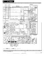
Page 13: ...Ii NOTES ON SCHEMATIC DIAGRAM can be found on page 8 l ANMERKUNGEN ZUM SCHEMATISCHEN SCHALTPLAN stehen auf Seite 8 OREMARQUES CONCERNANT LE DIAGRAMME SCHEMATIQUE sent indiqukes I la page 8 Playback 1 I 2 I 3 I 4 I 5 I 6 Figure 13 SCH 13 ...

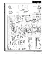
Page 14: ... 9 I 10 I 11 I 12 n 2 MAIN Pwe AI 0113 0213 2SC2878 B MUTING 0114 0214 2X2603 F MUTING JACK PWB A3 back Record APSS B 6 I I I 1 7 a 9 I 10 I 11 I 12 3 SCHEMATIC DIAGRAM l 2 14 _ _ _ __ _I _____ _ 1 _ _ 1_ I _ _ I_ ...

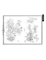
Page 15: ...I H 1 I 2 I 3 4 5 I 6 I I i f I I I I I 1 I 2 I 3 I 4 I il I Figure 15 WYRING SIDE OF 15 ...

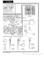
Page 16: ...I 7 I a I 9 I 10 I 11 I 12 f JACK PWS A3 I 7 I a I 9 I 10 I 11 I 12 I D E OF P W BOARD l 2 16 ...

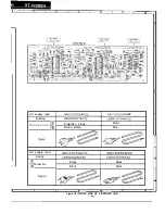
Page 17: ...re Projection stripe Brand stamp QACCVOOOI AGZZ LBSHC0004AGZZ Brown Blue AC supply lead Busing B Connection Figure QACCZ0053AFOO QACCZ0056AFOO I LBSHC0007AFZZ LBSHC0007AFZZ Black Block Black Black i3 1 7 I 8 I HIRING I P i BOARD I 11 I 12 Figure 18 SIDE OF 2 2 18 A B C D E F H ...

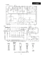
Page 18: ...UT qm 6 D B 4 2 3J IN OUT GNI IN IN rA7341P GND AMP Figure 19 l EQUIVALENT CIRCUIT BLOCK DIAGRAM OF IC 2sc2001 L 2SC2240 BL 2SC2878 B 288562 C LT SEGSlA LT 5PRZlA It 0 0 E C B mm 0 ECB mIILII 0 Figure 19 2 TYPES OF TRANSISTOR AND LED 19 ...

Page 19: ...I I 0 I n I m I 0 I 0 I W I D n L I I G I n I m I u I 0 I W I D ...

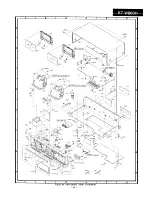
Page 20: ...2 I 31 606X41 w I 1 A 336 A ...

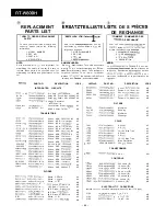
Page 21: ...on NPN 2SC2603 F AB 0213 VS2SC2878B 1 Silicon NPN 2SC2878 B AC Q214 219 VS2SC2603 F 1 Silicon NPN 2SC2603 F AB 0301 302 vs2sc2001 L 1 Silicon NPN 2SC2001 L A8 0401 402 VS2SA933SR 1 Silicon PNP 2SA933 SR AB Q403 405 VS2SC2603 F l Silicon NPN 2SC2603 F AB Q406 VS2SA933SR 1 Silicon PNP 2SA933 SR AB Q407 409 VS2SC2603 F 1 Silicon NPN 2SC2603 F AC 0410 411 VS2SA933SR 1 Silicon PNP 2SA933 SR AB 0412 413...

Page 22: ... AA A A AA AA AB AB AB AB AB AB 21I REF NO PART NO DESCRIPTION CODE C407 408 c409 c503 C506 C507 508 c509 510 C513 516 C601 602 C603 604 c701 c704 705 RC EZA106AFl C RC EZA475AFl E RC EZl 191 AFZZ RC GZA107AFl C RC EZA335AFl H RC EZA106AFl E RC GZAI 07AFl C RC EZA105AFl H RC EZA106AFl C RC EZA475AFl E RC EZA106AFl C 1 0 pF 1 6 V 4 7 PF 25V 2 2 0 0 pF 3 5 V 1 0 0 pF 1 6 V 3 3 pF 5 0 V 10 PF 2 5 V 1...

Page 23: ...A AA AB AA AA AB AA AA AA AA AA AA AA AA AA AA AA AA AA AA AA AA AA AA AA AA AA A A AA AA AA AA AA AA AA REF NO RI 32 R133 RI 3 5 RI 36 R137 R138 R139 R140 R141 R142 R143 RI44 RI 4 5 R146 RI 4 7 R148 R149 R150 R151 R152 R153 R154 R155 R156 R157 R158 R159 R160 R161 RI 6 2 R163 RI 6 4 RI 65 RI 66 RI 67 RI 6 8 Rl69 170 R171 RI 7 2 R173 RI 74 R175 R176 R177 RI 78 RI 79 RI 8 0 RI 81 R182 Rl84 RI 8 5 R1...

Page 24: ...A AA AA AA AA AA AA AA AA AA AA AA AA AA A A AA AA 25 REF NO R284 R285 R286 R287 R288 R289 290 R291 R292 R293 R294 R295 R296 R297 R298 R299 R301 302 R303 304 4 R305 R306 R307 R308 R309 310 R311 312 R401 R402 R404 R405 R406 R408 R409 410 R411 R412 413 R414 R415 R416 R417 419 R420 R421 R422 R423 R424 430 R431 R432 R433 435 R436 R437 R438 R439 R440 R441 R443 R444 R445 R446 R447 R448 R502 503 R504 R50...

Page 25: ... 16 X 8 SW8 9 QSW F021 GAFZZ Switch Leaf Type AB SW1 O l 2 QSW FOI 97AFZZ Switch Leaf Type AC SW1 3 QSW F021 GAFZZ Switch Leaf Type AB SW1 5 QSW FO663AFZZ Switch Push Type AG REF NO TE501 TPl TP2 1 2 3 4 5 6 7 8 9 10 11 12 13 14 15 16 17 18 19 2 0 21 2 3 2 4 25 2 6 27 2 8 2 9 3 0 31 3 2 33 3 4 35 36 37 38 3 8 3 9 4 0 41 41 4 2 4 3 4 4 4 5 4 6 4 7 4 8 4 9 5 0 51 52 53 5 4 55 5 6 57 58 PART NO DESCR...

Page 26: ...everse Turntable Take up Turntable Supply Flywheel Reverse Flywheel Forward Gear Fast Forward Rewrnd Gear Playback Gear Reduction Gear Clutch Gear Head Idler Playback Pulley Deck 2 Only Pulley Flywheel Belt Pinch Roller Forward A A AA AA AA AA 301 2 A A 301 3 AC 301 4 AB 301 5 AB 301 6 AB 301 7 AE 302 AC 303 AH 304 AH 305 AE 306 AA 307 AA 308 AA 309 AA 310 AD 311 AA 312 AC 313 AD 314 REF NO 123 12...

Page 27: ...AA A A AB AI3 AA AD A A AL AL AK AL AB AB AA AA A A AC AB AD A A A A AA REF NO 602 603 605 606 607 608 609 6 1 0 611 612 613 6 1 4 615 616 PART NO DESCRIPTION CODE LX NZOI 18AFFD XHBSD30PO6000 XHBSF30P06000 XHBSF30PO8000 XH BSMO PO8000 XHSSD30PO6000 XHSSD30PU8000 XJBSD26P08000 XJBSD3OPO8000 LX HZ0056AFFD XJBS33OPlZOOO XJBSF30PO8000 XJBS330P18000 XHBSF30PlOOOO Nut Jack S c r e w 3 X 6mm S c r e w 3...

Page 28: ... les sont partiellement changees Au moment de parer les mod les veuillez se reporter au Manuel de Service et B l autre Manuel de Service deja publie S3634RTW800HK DIFFERENCE BETWEEN JAPAN A ND KOREA DIJNTERSCHIED zwx3m JAPA N UND KOREA ODIFERENCE ENTRE JAPON ET COREE REF MADE IN JAPAN MADE IN KOREA DESCRIPTION NO PART NO 1 CODE 1 PART NO i CODE VHDlN4002 1 AB Silicon lN4002 VHDlN4002 1 AB Silicon ...

Reviews:

Related manuals for RT-W800H