– 81 –
SD-CX1W
FUNCTION TABLE OF IC
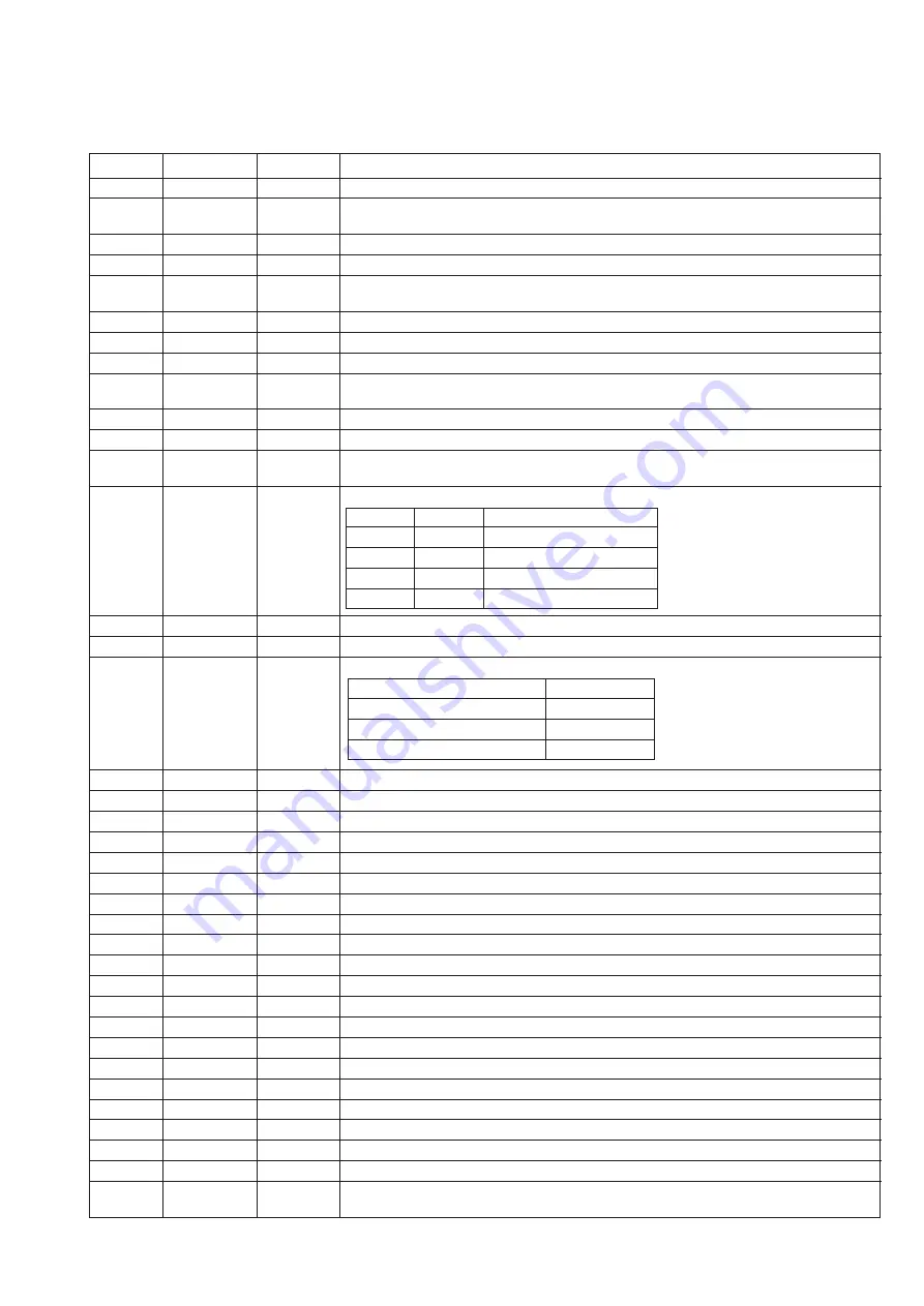
IC3 VHiTC9490F/-1: Servo/Signal Control (TC9490F) (1/2)
1
BCK
Output
Bit clock output terminal. 32 fs, 48 fs or 64fs can be selected by command.
2
LRCK
Output
L/R channel clock output terminal. L channel: "L", R channel: "H".
the output polarity can be inverted by command.
3
AOUT
Output
Audio data output terminal. MSB/LSB fast can be selected by command.
4
DOUT
Output
Digital out output terminal. Up to double speed can be output.
5*
IPF
Output
Correction flag output terminal. When the correction impossible symbol appears if the AOUT
output corresponds to the C2 correction output: "H".
6
VDD3
Input
Digital 3.3 V power supply terminal.
7
VSS3
—
Digital GND terminal.
8*
SBOK
Output
Subcode Q data CRCC decision result output terminal. When the decision result is OK: "H".
9*
CLCK
Input/Output
Clock input/output terminal for subcodes P-W data reading.
The input/output polarity can be selected by command.
10*
DATA
Output
Subcodes P-W data output terminal.
11*
SFSY
Output
Playback system frame sync signal output terminal.
12*
SBSY
Output
Subcode block sync output terminal.
In the S1 position when the subcode sync is detected: "H".
13
/HSO
Output
Playback speed mode flag output terminal.
14*
/UHSO
Output
15
PVDD3
Input
3.3 V power supply terminal for PLL system.
16
PDO
Output
EFM signal/PLCK signal phase error signal output terminal.
17
TMAX
Output
TMAX detection result output terminal.
18
LPFN
Input
Amp's inversion input terminal for PLL system low-pass filter.
19
LPFO
Output
Amp's output terminal for PLL system low-pass filter.
20
PVREF
Input
VREF terminal only for PLL system.
21
VCOF
Output
Filter terminal for VCO.
22
AVSS3
—
Analog GND terminal.
23
SLCO
Output
DAC output terminal for data slice level generation.
24
RFI
Input
RF signal input terminal. Zin can be selected by command.
25
AVDD3
Input
Analog 3.3 V power supply terminal.
26
RFCT
Input
RFRP signal center level input terminal.
27
RFZI
Input
Input terminal for RFRP signal zero crossing.
28
RFRP
Input
RF ripple signal terminal.
29
FEI
Input
Focus error signal input terminal.
30
SBAD
Input
Sub-beam addition signal input terminal.
31
TEI
Input
Tracking error input terminal. Fetch when the tracking servo is on.
32
TEZI
Input
Input terminal for tracking error signal zero crossing.
33
FOO
Output
Focus equalizer output terminal.
34
TRO
Output
Tracking equalizer output terminal.
35
VREF
Input
Analog reference power supply terminal.
36
RFGC
Output
RF amplitude adjustment control signal output terminal.
37
TEBC
Output
Tracking balance control signal output terminal.
38
SEL
Output
APC circuit ON/OFF signal output terminal.
When the laser is on, UHS="L": "Hi-z", UHS="H": "H" output.
Pin No.
Terminal Name
Function
Input/Output
In this unit, the terminal with asterisk mark (*) is (open) terminal which is not connected to the outside.
H
H
Normal speed playback
H
L
Double speed playback
L
L
4-time speed playback
—
—
—
/UHSO
/HSO
Playback speed
Longer than the specified period
"PVDD 3"
Within the specified period
"Hi-z"
Shorter than the specified period
"AVSS 3"
TMAX detection result
TMAX output
Summary of Contents for SD-CX1W(BL)
Page 114: ...SD CX1W 15 M E M O ...
Page 115: ...SD CX1W 16 M E M O ...

