– 85 –
SD-CX1W
1*
P77/AN7
—
Input (A/D Input)
“L” = Output fixed.
2
P76/AN6
KEY1
Input (A/D Input)
A/D KEY input 1.
3
P75/AN5
KEY2
Input (A/D Input)
A/D KEY input 2.
4
P74/AN4
KEY3
Input (A/D Input)
A/D KEY input 3.
5
P73/AN3
P-DWN
Output
Vref voltage cut when detecting a power failure at SYS STOP.
“H” = Normal state, “L” = Power failure.
6
P72/AN2
TUNER_SM
Input (A/D Input)
Tuner tuning level detection. Output “L”.
7
P71/AN0
PROTECT
Input (A/D Input)
Ignored for 500 msec after detecting an error and turning the power
ON.When the input voltage is 2.5 V or below, the power is turned OFF .
8
P70/AN0
SPAN
Input (A/D Input)
“L” in input.
9
PB3
POWER
Output
Control of connection/disconnection on the primary side of power
supply. “H” = Connection, “L” = Disconnection.
10
PB2/DA
H.P_SW
Input
Switch for headphone plug-in detection.
“H” = Headphone, “L” = Speaker.
11
P57/SRDY3/AN15
CD_OP/CL_SENS
Input (A/D Input)
Turnover voltage detection when locking the CD lid.
1.5 V or below = CLOSE, 3.8 V or more = OPEN.
12
P56/SCLK3/AN14
P56
Input
“L” = Output fixed.
13
P55/SOUT3/AN13
P55
Input
“L” = Output fixed.
14
P54/SIN3/AN12
P54
Input
“L” = Output fixed.
15
P53/SRDY2/AN11
MD_LOAD_SW
Input
MD LOAD SW detection. L -> H = DISC IN.
16
P52/SCLK2/AN10
MD_ST
Output
1. Beginning of tracks on CD: 20 msec. H output.
2. MD ON (RESET): 100 msec. H output.
17
P51/SOUT2/AN9
MD_SERACH
Output
CD PLAY: “L” (including CUE/REVIEW). Others: “H”.
18
P50/SIN2/AN8
MD_RESET
Output
MD RESET output.
19
P67/SRDY1/CS/SCLK12
MD_D_STB
Input
MD strobe input.
20
P66/SCLK11
MD_D_SCK
Output
MD clock output.
21
P65/SOUT1
MD_KDATA
Output
MD KEY data.
22
P64/SIN1
MD_DATA
Input
MD data input.
23
P63/CNTR1
CD_BUS3
Input/Output
Data input/output terminal for CD interface 3.
“L” output fixed except CD function.
24
P62/CNTR0
CD_BUS2
Input/Output
Data input/output terminal for CD interface 2.
“L” output fixed except CD function.
25
P61/PWM
CD_BUS1
Input/Output
Data input/output terminal for CD interface 1.
“L” output fixed except CD function.
26
P60
CD_BUS0
Input/Output
Data input/output terminal for CD interface 0.
“L” output fixed except CD function.
27
P47/T3OUT
CD_BUCK
Output
Clock output terminal for CD interface.
“L” output fixed except CD function.
28
P46/T1OUT
CD_CCE
Output
Chip enable output terminal for CD interface.
“L” output fixed except CD function.
29
P45/INT1/ZCR
P45
Input
Connected to GND.
30*
P44/INT4
—
Input
“L” output fixed.
31
P43/INT3
IC_CLK
Output
External control IC related clock.
SANYO C bus, input/output expande.
32
P42/INT2
REMOCON_IN
Input
Remote control input.
33
P41
IC_DI
Output
External control IC related DATA output.
SANYO C bus, input/output expander.
34
P40/INT0
SYS_STOP
Input
Microcomputer backup detection.
“H” = Normal state, “H” -> “L” = Power failure detection.
35
RESET
RESET
Input
Microcomputer reset terminal.
36
PB1/XCIN
IC_CE
Output
External control IC related chip enable output.
SANYO CCB bus.
37
PB0/XCOUT
IC_DO
Input
External control IC related DATA output.
SANYO CCB bus.
Pin
No.
Input/Output
Port Name
Terminal Name
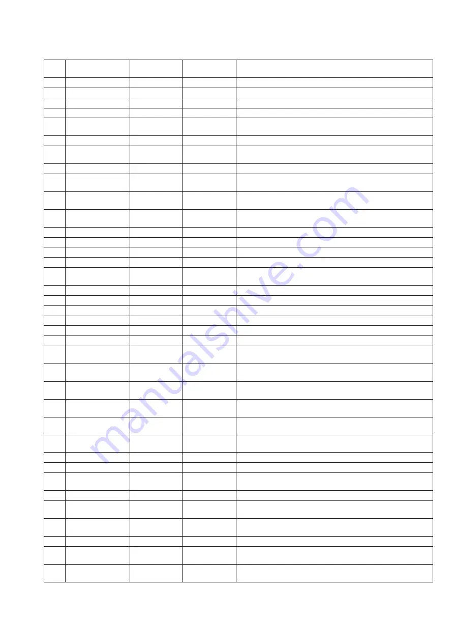
ICD01 RH-iX0376AWZZ: System Microcomputer (IX0376AW) (1/2)
Remarks
In this unit, the terminal with asterisk mark (*) is (open) terminal which is not connected to the outside.
Summary of Contents for SD-CX1W(BL)
Page 114: ...SD CX1W 15 M E M O ...
Page 115: ...SD CX1W 16 M E M O ...


