6. Duplex copy unit
3
2
1
16
17
4
12
5
8
7
6
9
15
14
13
10
11
Paper feed
roller
Takeup roller
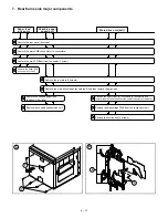
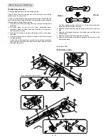
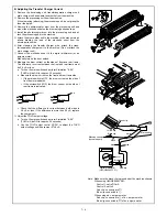
Remove the double side copy tray.
Remove the front cover (2 screws).
Unfasten two connectors.
Remove the pivot holding plate screw (one each on both sides).
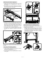
Remove the upper and transport paper guides from ADU.
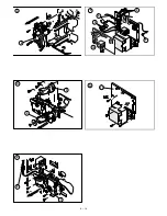
Remove the clutch stopper plate
(1 screw).
Remove the clutch side E-ring.
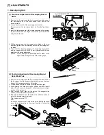
Move the bushing and take out the paper
feed roller drive shaft onto the front frame side.
Remove the paper feed roller.
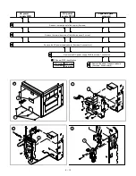
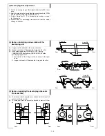
Remove the front and rear side two
counter roller tension springs.
Front frame Rear frame
Spring color
Black
White
Spring tension
Strong
Weak
Remove the counter roller.
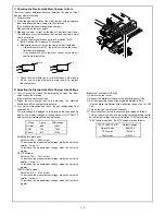
Remove the clutch retaining plate
(1 screw).
Loosen the setscrew and remove the
clutch.
Remove the takeup roller drive shaft
(2 on front, 1 on rear).
Push down the spring holder and remove
the takeup roller unit from ADU.
Remove the takeup roller arm side E-ring
(rear side).
Remove the paper holder arm side E-ring
(front and rear).
Remove the takeup roller.
Counter
roller
Install the assembly so the
protrusion on the clutch spring
faces down. The protrusion
should never face the transport
path.
NOTE:
12
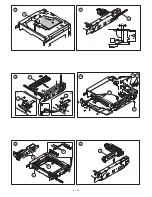
Remove the spring (2pcs.)
13
Remove the reversing roller.
6 – 11
Summary of Contents for SF-2040
Page 27: ...9 Desk unit SF D23 11 12 16 17 13 18 10 9 8 7 6 2 5 4 3 1 23 21 22 19 20 14 15 4 10 ...
Page 63: ...5 5 C F 10 D 7 6 11 G E 8 9 H 12 6 2 ...
Page 65: ...3 B 3 E 13 C 4 5 6 7 8 F 14 D 10 11 9 6 4 ...
Page 67: ...2 1 3 A D 9 8 11 10 B 4 5 E 12 13 14 C 7 6 6 6 ...
Page 69: ...A a 1 1 D 4 4 B 1 b 1 1 E 5 5 7 6 8 9 8 5 C 2 3 3 F 5 11 12 6 8 ...
Page 71: ...1 2 3 3 4 5 A D 13 11 10 7 6 6 7 B E 14 8 12 9 C F 15 G 16 16 6 10 ...
Page 73: ...A a 1 D 11 10 10 9 8 B 4 2 3 E 13 12 12 C 5 7 6 7 6 12 ...
Page 75: ...C 4 F 9 9 9 10 9 5 6 D G 11 E 8 7 6 14 ...
Page 78: ...Volume PWB 8 9 10 10 6 17 ...
Page 80: ...C 5 F 11 P D F R 7 6 6 12 13 G 12 13 E 8 9 a 8 H 14 6 19 ...


