A
1
1
C
4
B
3
D
5
1
4
2
3
5
AC power
supply PWB
DC power
supply PWB
Paper exit gate
solenoid
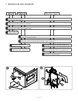
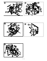
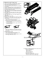
Remove the rear panel of the copier (6 screws).
Remove the rear side screw of the left side panel (1 screw).
Remove the AC power supply board (2 screws, 6 connectors).
Remove the DC power supply PWB (5 screws, 1 connector).
Remove the paper exit gate solenoid
(2 screws, 2 connectors).
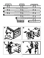
DC power PWB identification
100V system
White label
200V system
Red label
6 – 15
Summary of Contents for SF-2040
Page 27: ...9 Desk unit SF D23 11 12 16 17 13 18 10 9 8 7 6 2 5 4 3 1 23 21 22 19 20 14 15 4 10 ...
Page 63: ...5 5 C F 10 D 7 6 11 G E 8 9 H 12 6 2 ...
Page 65: ...3 B 3 E 13 C 4 5 6 7 8 F 14 D 10 11 9 6 4 ...
Page 67: ...2 1 3 A D 9 8 11 10 B 4 5 E 12 13 14 C 7 6 6 6 ...
Page 69: ...A a 1 1 D 4 4 B 1 b 1 1 E 5 5 7 6 8 9 8 5 C 2 3 3 F 5 11 12 6 8 ...
Page 71: ...1 2 3 3 4 5 A D 13 11 10 7 6 6 7 B E 14 8 12 9 C F 15 G 16 16 6 10 ...
Page 73: ...A a 1 D 11 10 10 9 8 B 4 2 3 E 13 12 12 C 5 7 6 7 6 12 ...
Page 75: ...C 4 F 9 9 9 10 9 5 6 D G 11 E 8 7 6 14 ...
Page 78: ...Volume PWB 8 9 10 10 6 17 ...
Page 80: ...C 5 F 11 P D F R 7 6 6 12 13 G 12 13 E 8 9 a 8 H 14 6 19 ...


