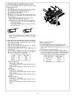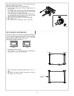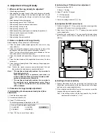
If La=Lb and Lc=Ld, no adjustment is required.
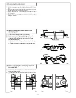
If La>Lb(Lc<Ld), rotate the eccentric roller in one direction to raise
the front frame side of the 4. and 5. mirror base unit.
If La<Lb(Lc>Ld), rotate the eccentric roller in the other direction to
lower the front frame side of the 4. and 5. mirror base unit.
Note: Remember how much the roller is rotated.
(One rotation of the roller causes the height of the front frame side
to change by 2 mm and the difference between La and Lb to
change by 4 mm).
*
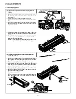
After opening the front cabinet, the adjustment described above
can be made through the access hole.
If the above procedure does not provide sufficient adjustment, fol-
low the steps shown below:
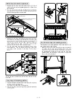
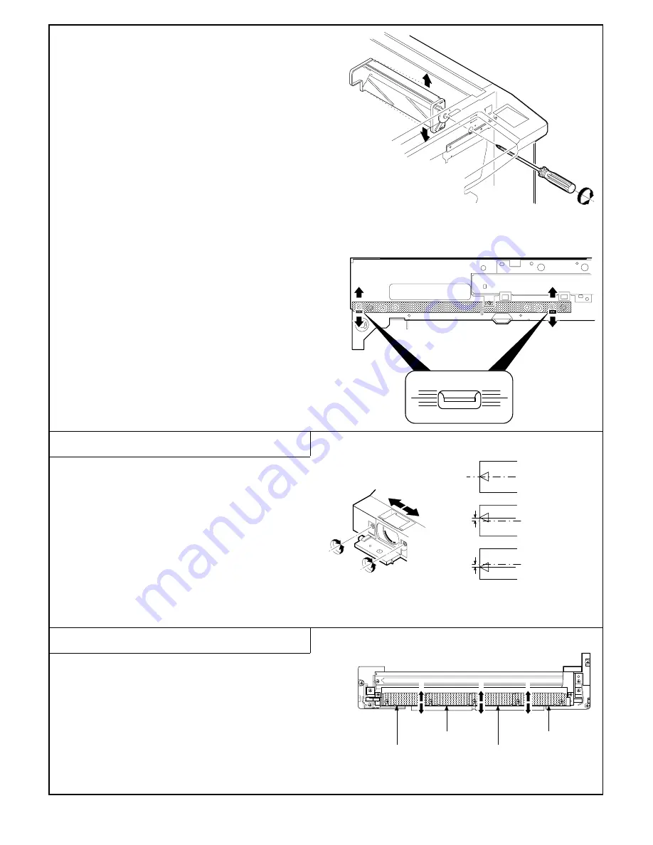
1
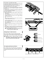
Move the B rail of the mirror base upward or downward (in the
arrow direction).
If La>Lb, raise the mirror base B rail on the paper discharge side
by one-half of (La-Lb).
If La<Lb, lower the mirror base B rail on the paper discharge
side by one-half of (Lb-La).
ex.:
When La=12 mm and Lb=9 mm, raise the mirror base B rail on
the paper discharge side by 1.5 mm.
If Lc>Ld, lower the mirror base B rail on the paper discharge
side by one-half of (Lc-Ld).
If Lc<Ld, raise the mirror base B rail on the paper discharge side
by one-half of (Ld-Lc).
(Grasping the grip of the mirror base rail, move the mirror base
rail).
2
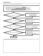
Adjust the eccentric roller as described in 1) until La=Lb and
Lc=Ld.
3
After adjustment, manually rotate the mirror base driving pulley
to check that the mirror base A and B do not come into contact
with each other during full-scanning motion.
Note: If the mirror base rail is moved excessively, the mir-
ror bases may contact with each other.
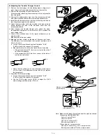
(9) Adjusting the Center Deviation
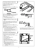
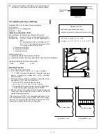
Take a full-size copy and compare the copy with the original.
If the deviation of the copy center from the original center is more
than 2mm, move the lens in the arrow direction so that the deviation
is 2 mm or less.
Note: After moving the lens, adjust the position of the blank
lamp because a change of the reference center position
results in a change of the blank lamp position.
(10) Adjusting the Exposure Balance
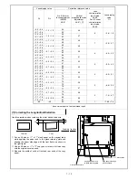
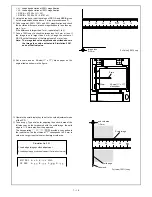
Take a half-tone copy, and move the exposure control plate a, b, c
and d to adjust the exposure balance. Movement of the plate in the
A direction provides less exposure and the B direction more ex-
posure.
Original center
(Original)
2 mm
or less
Copy paper center
(Copy 1) Move lens in the A direction
(Copy 2) Move lens in the B direction
Copy paper center
A
B
A
B
A
B
Exposure control plate (a)
Exposure control plate (b)
Exposure control plate (c)
Exposure control plate (d)
B
A
7 – 14
Summary of Contents for SF-2040
Page 27: ...9 Desk unit SF D23 11 12 16 17 13 18 10 9 8 7 6 2 5 4 3 1 23 21 22 19 20 14 15 4 10 ...
Page 63: ...5 5 C F 10 D 7 6 11 G E 8 9 H 12 6 2 ...
Page 65: ...3 B 3 E 13 C 4 5 6 7 8 F 14 D 10 11 9 6 4 ...
Page 67: ...2 1 3 A D 9 8 11 10 B 4 5 E 12 13 14 C 7 6 6 6 ...
Page 69: ...A a 1 1 D 4 4 B 1 b 1 1 E 5 5 7 6 8 9 8 5 C 2 3 3 F 5 11 12 6 8 ...
Page 71: ...1 2 3 3 4 5 A D 13 11 10 7 6 6 7 B E 14 8 12 9 C F 15 G 16 16 6 10 ...
Page 73: ...A a 1 D 11 10 10 9 8 B 4 2 3 E 13 12 12 C 5 7 6 7 6 12 ...
Page 75: ...C 4 F 9 9 9 10 9 5 6 D G 11 E 8 7 6 14 ...
Page 78: ...Volume PWB 8 9 10 10 6 17 ...
Page 80: ...C 5 F 11 P D F R 7 6 6 12 13 G 12 13 E 8 9 a 8 H 14 6 19 ...

