SJD24NSLG
5 – 1
SJD24NSLG
Service Manual
CHAPTER 5.
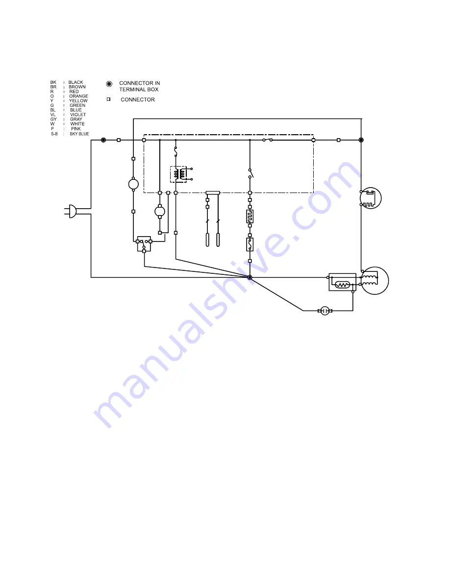
WIRING DIAGRAM
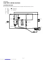
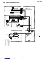
[1] WIRING DIAGRAM
Be sure to replace the electrical parts with specified ones for maintaining the safety and performance of the set.
SOURCE CORD
(BR)
FAN MOTOR FM
(O)
DOOR SWITCH
(BR)
L
LAMP
(S-B)
(BL)
DEF-THERMIST
OR
R-THERMIST
OR
2
2
FUSE
(W)
DEF-HEATER
(BK)
PWB
STARTING RELAY
COMPRESSOR
PROTECTOR
(GY)
RUNNING CAPACITOR


