SJPT55RHS
9 – 6
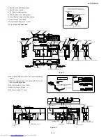
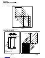
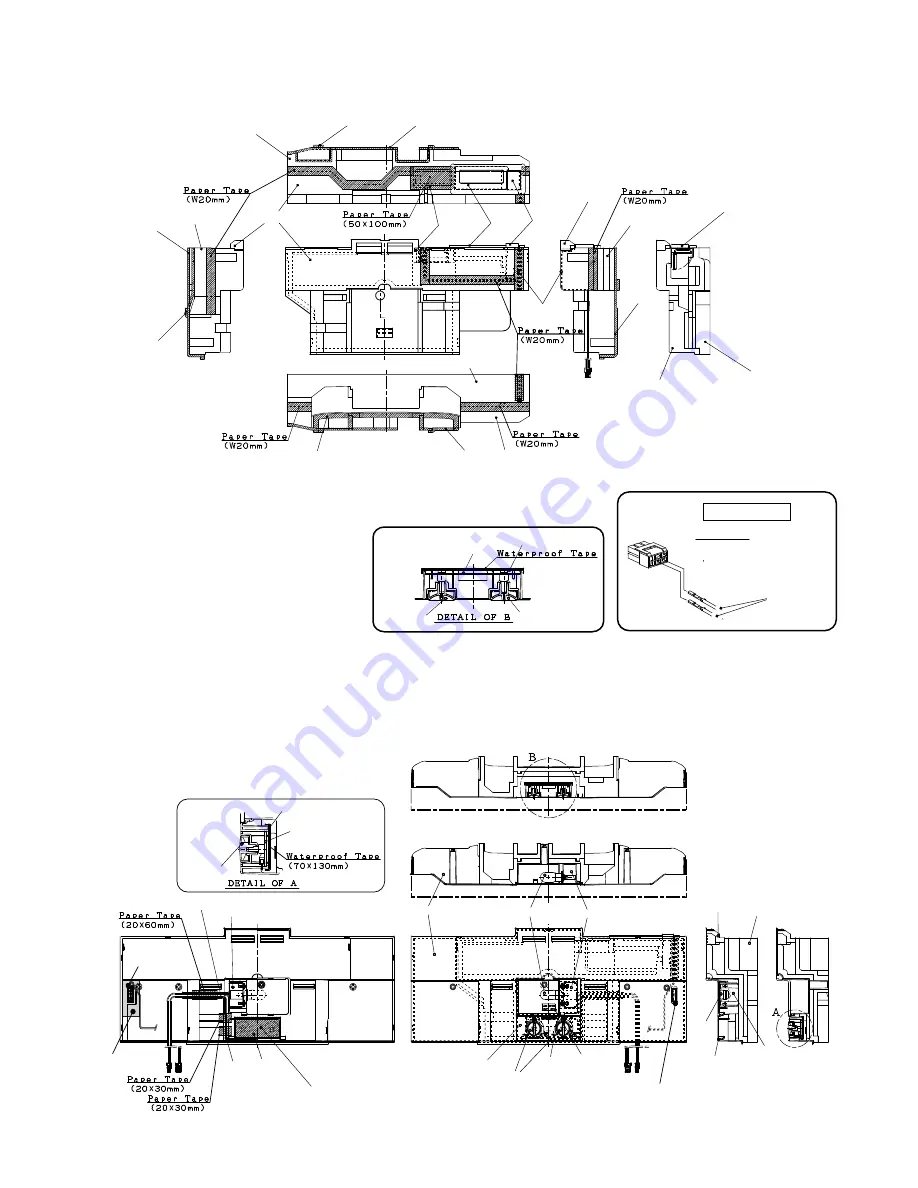
7) Insert 6) ass'y to 4) ass'y.
8) Stick A-sealer damper to 7) ass'y.
9) Fix 8) ass'y with paper tape.
Figure A-15
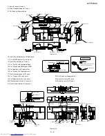
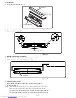
10) Insert Control harness to VR PWB ass'y.
11) Fix VR PWB ass'y to R-c box cover.
12) Insert Control knob to 11) ass’y.
13) Fix 12) ass'y with Waterproof tape.
14) Fix 13) ass'y with PWB sheet 55DR.
15) Fix Lamp ass'y to R lamp holder.
16) Fix 15) ass'y to 2 Tapping screws.
17) Insert Lamp harness to 16) ass'y.
18) Fix 17) ass'y to R-c box cover.
19) Fix R-thermistor to R-c box cover.
20) Stick Warning label to R-c box cover.
21) Stick Control label to R-c box cover.
22) Fix (21) ass'y with paper tape.
23) Insert (9) ass'y to (22) ass'y.
24) Fix Lamp cover to (23) ass'y.
Figure A-16
Ra-sealer a
R air guider b
Ra-sealer b
R air guider a
R air guider b
Ra-sealer b
Ra-sealer a
Damper
ass’y
A sealer
damper
R air
guider c
R air guider a
R air guider b
Damper ass’y
R air guider b
R air guider a
Damper
harness
Ra-sealer a
R air guider b
R air guider a
Ra-sealer b
Ra-sealer a
R-thermistor
Insert of pin
Note
Control knob
Control knob
PWB sheet 55DR
Pins should be insert surely,
and check by pulling it.
PL process
VR PWB ass’y
R-thermistor
sealer
R-thermistor
R-thermistor
Control knob
PWB sheet 55DR
Lamp harness
R lamp holder
Control label
Control knob
R-c box cover
R lamp
holder
R air guider b
R air guider a
R lamp holder
R-c box cover
VR PWB ass’y
VR PWB
ass’y
Control
harness
PWB sheet
55DR
Lamp
ass’y
Warning
label
Tapping
screw
Lamp ass’y


