TM150
ADJUSTMENTS, PERFORMANCE CHECK, AND FIRMWARE UPGRADE
2 – 10
CONFIDENTIAL
DRAFT
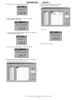
4.
When the rewrite operation starts, handset display screen shows
the software version and process of communications with the PC.
Canceling the ongoing rewrite operation:
Click the [QUIT] button.
To rewrite MOT files later, remove and install the battery first.
[Notes for the use of a cable for upgrading]
1.
Disconnect the AC charger from the cable. Otherwise charging
starts and the MOT file rewrite operation is interrupted.
2.
Make sure the handset battery is sufficiently charged.
If the battery is low, the rewrite operation may fail. Charge the bat-
tery before the operation.
3.
If the ongoing rewrite operation is canceled, or interrupted by an
error, remove and reinstall the battery and retry.
[Notes for the use of the Communication Box]
1.
When "Press Power Button!" appears, turn on Communication Box
SW from No.10 down to No.1. If the communication BoxSW No.1 is
first turned on, the rewrite on communication BoxSW No. 2 to No. 10
operation will fail.
2.
The time to delete the program data varies between handsets. If the
process fails at the default Wait Time (3 seconds), increase the
value.
Consequently, this will increase the time to complete the rewrite
operation.
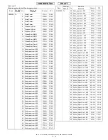
5) Checking the value of SUM
When the rewrite operation is completed, a confirmation message
appears with SUM.
SUM also appears on handset.
<When using a cable for upgrading>
After 8 seconds, SUM disappears.
<When using Communication Box>
When SET POWER SW is turned off, SUM disappears.
Make sure SUM is the same between the PC and handset.
The same SUM means that the rewrite operation is completed properly.
If the value is different, try again to ensure completion of the operation.
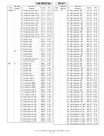
If the MOT file rewrite operation fails, an error message appears on
handset.
*
The screen shot on the left shows an error in erasing Flash data.
[ADR] and [STR] appear only when an error occurs in the FLASH-
related operation.
Start over the MOT file rewrite operation.
<When other error messages appear>
Find the message in 4-4-4. 2)Error messages for Loading loader, and
follow the instructions.
Error screen
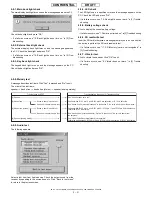
6) After the operation
Disconnect the cable for upgrading from handset.
When using the Communication Box, turn off SET POWER SW and
then disconnect the cable from handset.
Flash Loader 5.02
XXXXXXXCommand
Flash Loader 5.02
SUM Check End
SUM = 0xdb3d
Flash Loader 5.02
FLASH_ERROR
ERROR_ERASE
ADR = 0x1000000
STR = 0xA0
Summary of Contents for TM150
Page 61: ...TM150 CIRCUIT DIAGRAM AND PWB LAYOUT 5 13 CONFIDENTIAL DRAFT MAIN PWB_FRONT ...
Page 62: ...TM150 CIRCUIT DIAGRAM AND PWB LAYOUT 5 14 CONFIDENTIAL DRAFT MAIN PWB_REAR ...
Page 63: ...TM150 CIRCUIT DIAGRAM AND PWB LAYOUT 5 15 CONFIDENTIAL DRAFT LCD PWB_FRONT ...
Page 64: ...TM150 CIRCUIT DIAGRAM AND PWB LAYOUT 5 16 CONFIDENTIAL DRAFT LCD PWB_REAR ...


