TM150
ADJUSTMENTS, PERFORMANCE CHECK, AND FIRMWARE UPGRADE
2 – 24
CONFIDENTIAL
DRAFT
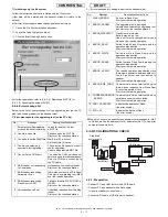
3.
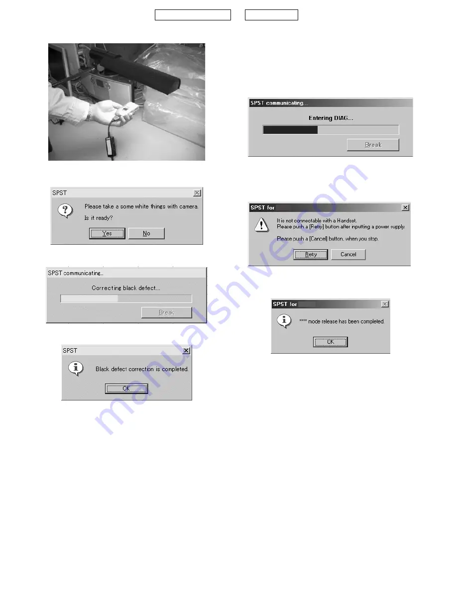
Hold the handset in the proper position.
4.
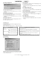
Click the "Black defect correction" button.
The following message is displayed.
5.
Click the "Yes" button. Communication starts.
6.
The result is displayed within a minute as follows.
When an error occurs, the corresponding message appears. Solve the
problem according to "Solution".
• Error 1
• Error 2
• Error 3
4-9.
****
MODE RELEASE
When the handset does not turn on and enter the normal mode, use this
function to change
****
mode to the normal mode.
<Operation>
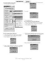
1) Select the COM port on the SPST initial screen and click
"
****
mode release". The following dialog box appears.
2) If SPST cannot communicate with the handset, the following mes-
sage is displayed. Make sure the handset is turned on and click
"Retry". To exit, click "Cancel".
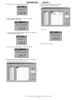
3) When complete, the following message appears.
5. OTHER TESTS
SPST does not provide tests of Bluetooth/USB communication.
Check them according to the following instructions.
5-1. USB
Connect TM150 and a PC with a USB cable. Check that TM150 is
recognized as a device.
If the USB driver for TM150 (SHARP GSM GPRS USB Driver) is not
installed on the PC, “Found New Hardware” window appears and
“Found New Hardware Wizard“ starts (the handset is recognized).
Error message : "There are too many black cracks."
Cause
: The light is too weak or strong.
Solution
: At the proper distance from the light source (8,000-
10,000 lux), perform black defect correction again.
Error message : "There are many black cracks."
Cause
: The light is too weak or strong.
Solution
: At the proper distance from the light source
(8,000 - 10,000 lux), perform black defect correction again.
Error message : "There are too many black cracks cannot be rectified."
Cause
: There is a hardware error.
Solution
: Replace the camera unit.
TM150
TM150
Summary of Contents for TM150
Page 61: ...TM150 CIRCUIT DIAGRAM AND PWB LAYOUT 5 13 CONFIDENTIAL DRAFT MAIN PWB_FRONT ...
Page 62: ...TM150 CIRCUIT DIAGRAM AND PWB LAYOUT 5 14 CONFIDENTIAL DRAFT MAIN PWB_REAR ...
Page 63: ...TM150 CIRCUIT DIAGRAM AND PWB LAYOUT 5 15 CONFIDENTIAL DRAFT LCD PWB_FRONT ...
Page 64: ...TM150 CIRCUIT DIAGRAM AND PWB LAYOUT 5 16 CONFIDENTIAL DRAFT LCD PWB_REAR ...


