TM150
OTHERS
6 – 5
CONFIDENTIAL
DRAFT
■
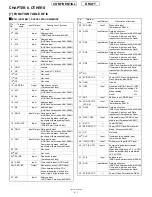
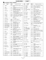
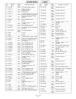
IC106 (AD6529B): DIGITAL BASEBAND
Pin
No.
Terminal
name
Input/
Output
Description of terminal
1
ASDO
Output
Audio serial port data output to ana-
log BB
2
BSDI
Input
Baseband serial port data input from
analog BB
3
BSOFS
Output
Baseband serial port output framing
signal output to analog BB
4
GPIO_48
Input
Hook switch of hands free kit
(earphone) detection
5
VINT
Input
Analog BB interface power supply
1.7 - 3.3 V (VCORE)
6
GPO_29
Output
Analog BB reset output (ABBRESET)
7
GPO_5
Output
Advanced state machine of analog BB
8
VDDRTC
Input
RTC power supply 1.0 - 1.9 V
(VRTC)
9
VSSRTC
-
RTC ground
10
MC_DAT[0]
Input/
Output
SD interface data bus 0
11
GPIO_22
Output
RSP for main LCD controller
12
GPIO_56
Input
Boot control 2
(Hardware version select)
13
KEYPADCOL[4]
Output
KEYIN signal output 4
14
KEYPADCOL[1]
Output
KEYIN signal output 1
15
KEYPADROW[4]
Input
KEYIN signal input 4
16
KEYPADROW[2]
Input
KEYIN signal input 2
17
GPIO_38
Input
Interrupt input from sound
generator IC
18
GPIO_36
Output
Mode select 2 for interface IC/
AOUT3 bias control
19
ASDI
Input
Audio serial port data input from
analog BB
20
GPIO_35
Input
SD card interface write protect
21
ADD[0]
Output
Write protect control for flash
memory 2
22
ASFS
Input
Audio serial port framing signal
input from analog BB
23
BSIFS
Input
Baseband serial port input framing
signal input from analog BB
24
BSDO
Output
Baseband serial port data output to
analog BB
25
CSDI
Input
Control serial port data input from
analog BB
26
GPO_6
Output
Not used
27
GPO_0
Output
Analog baseband receive section
control (RXON)
28
OSCOUT
Output
32.768 kHz crystal oscillator output
29
MC_DAT[2]
Input/
Output
SD interface data bus 2
30
VMC
Input
SD card interface power supply
1.7 - 3.3 V (VAPP)
31
VCC
Input
Core power supply 1.7 - 1.9 V
(VCORE)
32
KEYPADCOL[3]
Output
KEYIN signal output 3
33
KEYPADCOL[2]
Output
KEYIN signal output 2
34
GPIO_39
Output
USB PU control for interface IC
35
GPIO_37
Input
Interrupt input from analog BB
36
GPIO_34
Output
UART_TXD for Bluetooth module
37
ADD[4]
Output
Processor address bus 4
38
ADD[2]
Output
Processor address bus 2
39
GND
-
Ground
40
KEYPADROW[0]
Input
KEYIN signal input 0
41
VEXT
Input
System interface power supply
2.4 - 3.3 V (VINT)
42
GPO_23
Output
SLEEP control for SRAM 2
43
ADD[7]
Output
Processor address bus 7
44
VMEM
Input
Memory power supply 2.7 - 3.3 V
(VMEM)
45
ADD[1]
Output
Processor address bus 1
46
CSDO
Output
Control serial port data output to
analog BB
47
CLKOUT_GATE
Input
Master clock enable from analog
BB (MCLKEN)
48
GPO_1
Output
Analog baseband transmit
section control (TXON)
49
OSCIN
Input
32.768 kHz crystal oscillator input
50
MC_CMD
Input/
Output
SD interface CMD (SD_CMD)
51
GPIO_55
Input
Boot control 1
(Hardware version select)
52
GND
-
Ground
53
KEYPADROW[3]
Input
KEYIN signal input 3
54
KEYPADROW[1]
Input
KEYIN signal input 1
55
GPIO_33
Input
UART_RXD for Bluetooth module
56
GPIO_17
Output
PCM d ata o utp ut fo r Blu eto oth
module
57
ADD[11]
Output
Processor address bus 11
58
ADD[9]
Output
Processor address bus 9
59
ADD[5]
Output
Processor address bus 5
60
ADD[3]
Output
Processor address bus 3
61
GND
-
Ground
62
VCC
Input
Core power supply 1.7 - 1.9 V
(VCORE)
63
PWRON
Output
System power control for analog
BB
64
MC_DAT[1]
Input/
Output
SD interface data bus 1
65
GND
-
Ground
66
VEXT
Input
SIM power supply 2.4 - 3.3 V
(VINT)
67
KEYPADCOL[0]
Output
KEYIN signal output 0
68
VEXT
Input
SIM power supply 2.4 - 3.3 V
(VINT)
69
GPIO_15
Input
PCM data input for Bluetooth
module
70
GPIO_16
Output
PCM SYNC output for Bluetooth
module
71
ADD[13]
Output
Processor address bus 13
72
ADD[12]
Output
Processor address bus 12
73
ADD[8]
Output
Processor address bus 8
74
ADD[6]
Output
Processor address bus 6
Pin
No.
Terminal
name
Input/
Output
Description of terminal
*
Summary of Contents for TM150
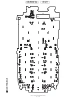
Page 61: ...TM150 CIRCUIT DIAGRAM AND PWB LAYOUT 5 13 CONFIDENTIAL DRAFT MAIN PWB_FRONT ...
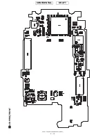
Page 62: ...TM150 CIRCUIT DIAGRAM AND PWB LAYOUT 5 14 CONFIDENTIAL DRAFT MAIN PWB_REAR ...
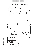
Page 63: ...TM150 CIRCUIT DIAGRAM AND PWB LAYOUT 5 15 CONFIDENTIAL DRAFT LCD PWB_FRONT ...
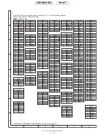
Page 64: ...TM150 CIRCUIT DIAGRAM AND PWB LAYOUT 5 16 CONFIDENTIAL DRAFT LCD PWB_REAR ...


