TM150
OTHERS
6 – 19
CONFIDENTIAL
DRAFT
In this unit, the terminal with asterisk mark (
*
) is (open) terminal which
is not connected to the outside.
■
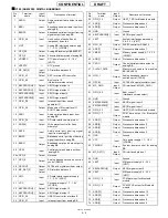
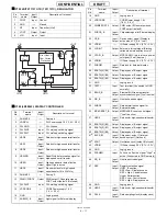
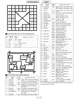
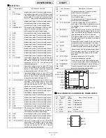
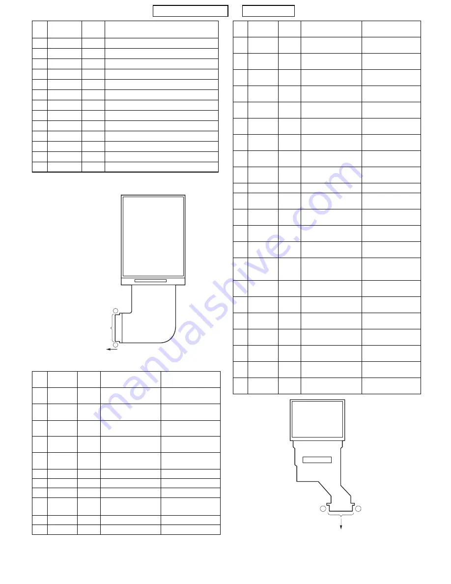
LCD001 RLCUB0049AFZZ : EXTERNAL DISPLAY
47
C4-
-
Booster capacitor connection terminal
48
C4+
-
Booster capacitor connection terminal
49
C3-
-
Booster capacitor connection terminal
50
C3+
-
Booster capacitor connection terminal
51
C2-
-
Booster capacitor connection terminal
52
C2+
-
Booster capacitor connection terminal
53
C1-
-
Booster capacitor connection terminal
54
C1+
-
Booster capacitor connection terminal
55
VDC2
Output DC/DC converter output
56
VDC2
Output DC/DC converter output
57
VR
Output Reference power supply output
58
VS
Output Source power supply output
59
VS
Output Source power supply output
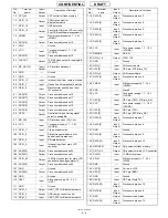
Pin
No.
Terminal
name
Input/
Output
Description of
terminal
Notes
1
V0
-
Display drive power
supply terminal
-
2
V1
-
Display drive power
supply terminal
-
3
V2
-
Display drive power
supply terminal
-
4
V3
-
Display drive power
supply terminal
-
5
V4
-
Display drive power
supply terminal
-
6
GND
-
Ground
-
7
RESB
Input
Reset signal
-
8
CSB
Input
Chip select signal
-
9
RS
Input
Register select signal "0": Display RAM data
"1": Command data
10
WRB
Input
Write signal
"L": Activated
11
RDB
Input
Read signal
"L": Activated
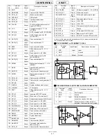
Pin
No.
Terminal
name
Input/
Output
Description of terminal
MAIN DISPLAY
59
1
To InputTerminal
12
D0
Input/
Output
Data signal
-
13
D1
Input/
Output
Data signal
-
14
D2
Input/
Output
Data signal
-
15
D3
Input/
Output
Data signal
-
16
D4
Input/
Output
Data signal
-
17
D5
Input/
Output
Data signal
-
18
D6
Input/
Output
Data signal
-
19
D7
Input/
Output
Data signal
-
20
LP
Input/
Output
Latch signal
-
21
FLM
Output Display sync signal
-
22
G N D
(VSS)
-
Ground
-
23
CK
Input
Master clock
external input terminal
-
24
CKS
Input
Ma ste r cl o ck i np u t
selection terminal
"L": Built-in oscillation
25
VDD/VEE
-
Logic system power
supply terminal
-
26
VREG
Output Output terminal for
generating constant
voltage
-
27
VOUT
Output Built-in step-up circuit
output terminal
-
28
CAP1
-
Output Booster capacitor con-
nection terminal (
-
)
-
29
CAP1+
Output Booster capacitor con-
nection terminal (+)
-
30
CAP2
-
Output Booster capacitor con-
nection terminal (
-
)
-
31
CAP2+
Output Booster capacitor con-
nection terminal (+)
-
32
CAP3
-
Output Booster capacitor con-
nection terminal (
-
)
-
33
CAP3+
Output Booster capacitor con-
nection terminal (+)
-
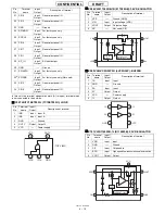
Pin
No.
Terminal
name
Input/
Output
Description of
terminal
Notes
To Input Terminal
1
EXTERNAL
DISPLAY
33
Summary of Contents for TM150
Page 61: ...TM150 CIRCUIT DIAGRAM AND PWB LAYOUT 5 13 CONFIDENTIAL DRAFT MAIN PWB_FRONT ...
Page 62: ...TM150 CIRCUIT DIAGRAM AND PWB LAYOUT 5 14 CONFIDENTIAL DRAFT MAIN PWB_REAR ...
Page 63: ...TM150 CIRCUIT DIAGRAM AND PWB LAYOUT 5 15 CONFIDENTIAL DRAFT LCD PWB_FRONT ...
Page 64: ...TM150 CIRCUIT DIAGRAM AND PWB LAYOUT 5 16 CONFIDENTIAL DRAFT LCD PWB_REAR ...

