UP-3301US
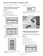
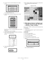
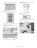
SERVICE PRECAUTION
– 16 –
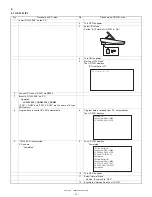
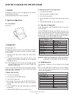
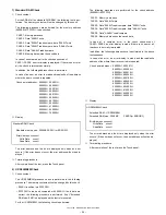
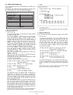
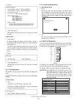
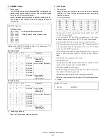
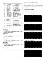
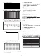
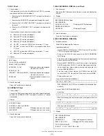
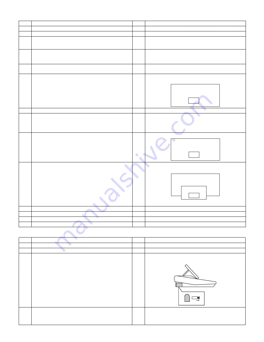
4.2 UP-T80BP LOGO
4.3 UP-T80BP IPL
No
Procedure on P.C. side
No
Procedure on UP-3301 side
1
Install “UTL33.EXE” on the P.C.
2
Enter the SRV mode. Then turn OFF the power or UP-3301.
3
While pressing the On-Line key, tum ON the power of UP-3301.
Keep pressing the On-Line key, and then press the Feed key
also. (Don’t move a finger from the On-line key.)
4
UP-T80BP enters into LOGO mode.
UP-T80BP prints out
“
****************
”.
5
Go into “UP-T80BP Utility mode”.
Select “6 UP-T80BP Utility” in SRV mode.
6
Starting of “UP-T80BP Utility mode”.
UP-3301 shows
7
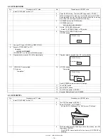
Connect P.C. and UP-3301 via RS232 (CH2).
8
Execute “UTL33.EXE” on P.C.
Operation:
>UTL33 LOGO.BMP
(“LOGO.BMP” is a file name of Bit-Map image.)
9
Program data is sent to UP-3301 automatically.
9
Program data is received from P.C. automatically.
10
“UTL33.EXE” is completed.
P.C. shows
“Completed.”
10
UP-3301 shows
“Completed.”
And UP-T80BP prints out the LOGO image.
11
Touch “OK” button.
12
Touch “EXIT” button.
13
Turn OFF the power of UP-3301.
14
Execute “Master Reset” on UP-T80BP.
No
Procedure on P.C. side
No
Procedure on UP-3301 side
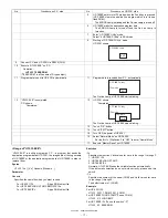
1
Install “UTL33.EXE” on the P.C.
2
Turn OFF the power of UP-3301.
3
Select “IPL Mode” on UP-T80BP.
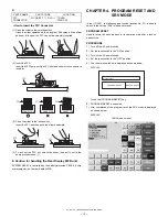
Set the Bit 1 of DipSwitch 2 to “ON” to enter “IPL Mode”.
4
While pressing both the Feed key and the On-Line key, turn ON
the power of UP-3301.
The ERROR Lamp and the On-line Lamp of UP-T80BP is
blinking.
UP-T80BP Utility
EXIT
UP-T80BP Utility
Normal mode
EXIT
UP-T80BP Utility
Normal mode
EXIT
Complete
OK
IPL SW
ON
IR Filter
Summary of Contents for UP-3301
Page 91: ...UP 3301US PWB LAYOUT 89 CHAPTER 9 PWB LAYOUT 1 MAIN PWB A side ...
Page 92: ...UP 3301US PWB LAYOUT 90 B side 8 CUSTOMER DISPLAY PWB ...
Page 93: ...UP 3301US PWB LAYOUT 91 2 IR PWB 3 LCD PWB A Side B Side 4 INVERTER PWB A Side B Side ...
Page 94: ...UP 3301US PWB LAYOUT 92 5 MOTHER PWB 6 N F PWB 7 TOUCH PANEL PWB ...
Page 95: ...UP 3301US PWB LAYOUT 93 ...
Page 111: ......


