UP-3301US
CIRCUIT DESCRIPTION
– 58 –
3-6. Extended I/O area
The addresses from F00000h to FFFFFFh are called an extended I/O area. The UP-3301 uses the following addresses as the break address register
(BAR) for SSP.
• FFFF00h ~ FFFFFFh
4. LCD display
The main display is a 640 x 480 dot liquid crystal display.
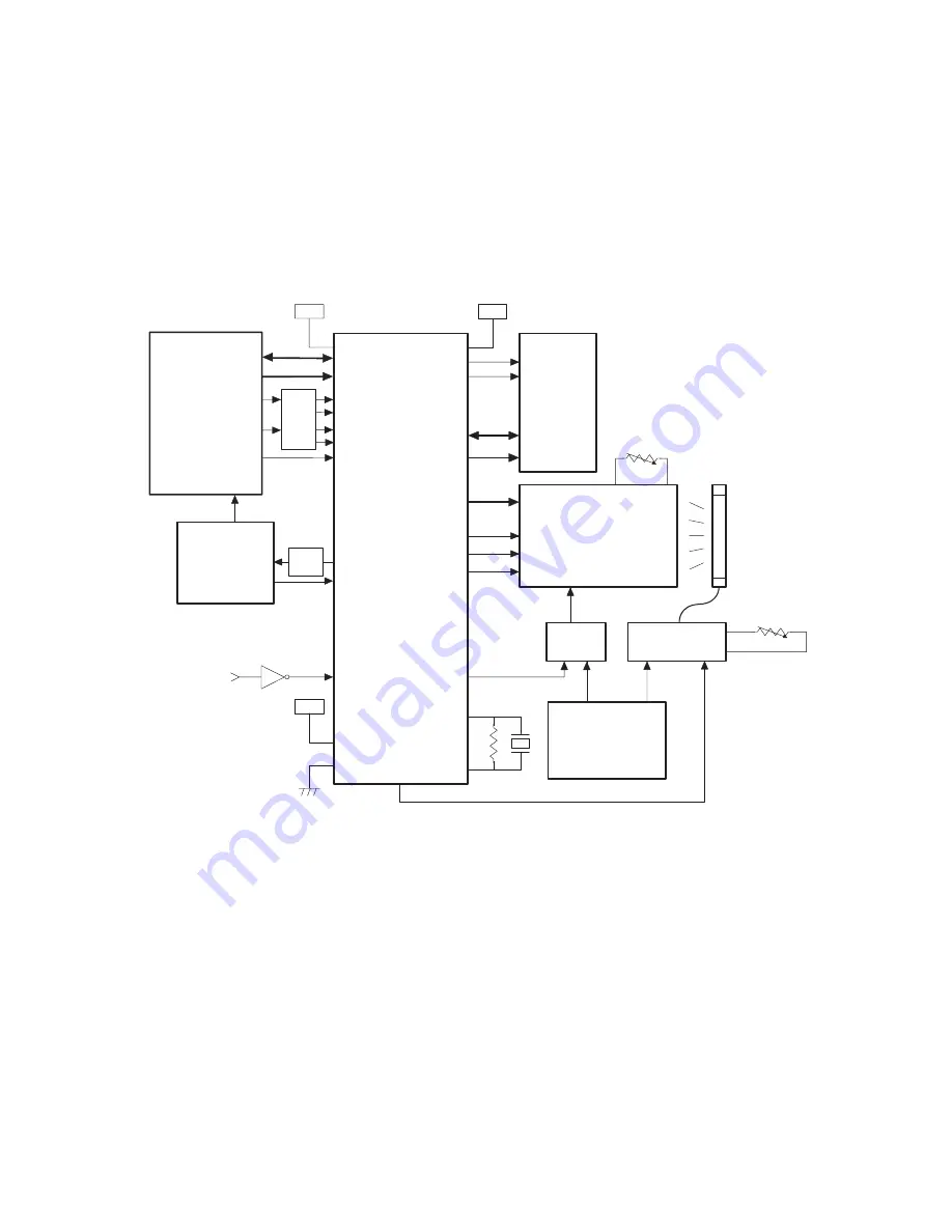
4-1. Block diagram
Here is the block diagram of the LCD and its associated components.
Fig. 7
4-2. LCD panel
The dot-matrix LCD unit LM10V33 with color STN and CCFT back light
is used for the LCD panel. The resolution provided is 640 x 480.
4-3. Display controller
The Matsushita VGAC (MN89303A) is used for the display controller.
VRAM is on the address space of the CPU and data can be written on
and read from it by every 128 KB of bank at the address C00000H ~
C1FFFFH from the CPU side. VRAM consists of 4 banks.
4-4. LCD ON control
The LCD’s bias power supply is controlled by the MN89303A terminal
LCDON to turn the LCD screen on and off.
The LCDON is at “L” res5V power is supplied to the LCD by set-
ting the expanded function control register bit5 of MN89303A to “H” with
software. The LCD screen isn’t turned on until +5V is supplied.
4-5. Back light control
The back light is turned ON/OFF by the MN89303A. The initial value is
“L” and the back light is off. By setting the expanded function control
register bit6 of the MN89303A to “H”, the inverter unit is turned on.
4-6. Luminance and contrast adjustment
5. Customer display
The customer display uses the NEW TYPE 2 LINE vacuum fluorescent
tube. The display is turned on and off by the CKDC9.
SD0~SD15
SA0~SA16
IORD-
MEMRD-
IOWR-
CLK
READY
RESET
RAS/CAS
WE-
UD0~UD7
LP
FP
DCLK
LCDON
OSC1
OCS2
MEMWR-
VCC
VCC
VCC
RAS-/CAS-
WE-
D0~D7
A0~A9
RD-
WR-
WAITZ
Φ
WAIT-
VWAITZ
RFSH-
RESET-
25MHz
+12V
+5V
(LCD ON/OFF)
VCC
Contrast
CPU
H8/510
MPCA8
MN89393A
VRAM
(DRAM512KB)
LCD
(640 x 480)
LOGIC
INVERTER
POWER
SUPPLY
(BACK LIGHT ON/OFF)
Luminance
RFSH-
MD0~MD15
MA0~MA9
LD0~LD7
UD0~UD7
LD0~LD7
LP
YD
XCK
BACKON
ISP
2032
ISP
2032
• Luminance: Luminance is adjusted with an inverter which has a
dimming function.
• Contrast:
Contrast is adjusted by controlling the contrast adjust-
ment voltage (VCON) of the LM10V33.
Summary of Contents for UP-3301
Page 91: ...UP 3301US PWB LAYOUT 89 CHAPTER 9 PWB LAYOUT 1 MAIN PWB A side ...
Page 92: ...UP 3301US PWB LAYOUT 90 B side 8 CUSTOMER DISPLAY PWB ...
Page 93: ...UP 3301US PWB LAYOUT 91 2 IR PWB 3 LCD PWB A Side B Side 4 INVERTER PWB A Side B Side ...
Page 94: ...UP 3301US PWB LAYOUT 92 5 MOTHER PWB 6 N F PWB 7 TOUCH PANEL PWB ...
Page 95: ...UP 3301US PWB LAYOUT 93 ...
Page 111: ......


