10. WAIT CONTROL
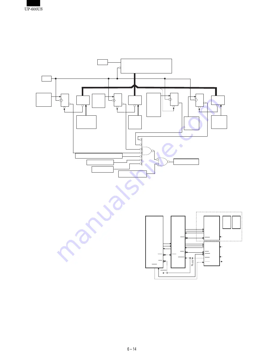
The weight control function built in the MPCA9 is used to provide an
interface with low-speed devices.
1) BLOCK DIAGRAM
The block diagram of the wait control function is shown.
In the figure, the decoder, wait enabling register, AND-OR sections
are the same as those in the MPCA6 or 7, but other components are
newly incorporated in the MPCA5.
EXWAITZ and WAITZ are external weight signals which are to be
ORed inside the MPCA9 and output to the WAITZ. The EXWAITZ is a
general-purpose wait request terminal, and WAITZ is the wait request
signal from the VGA controller.
11. CKDC9
The UP-600 uses one CKDC9 for the CKDC PWB and one CKDC9
for the for POLE display (option) to carry out the following control
operations.
CKDC PWB:
•
Clock (second data readable)
•
Buzzer
•
System reset
•
Key/Clerk switch
Display PWB:
•
Customer display tube
•
Pole display (UP-P16DP)
1) INTERFACE
The CKDC9 is connected through the MPCA8.
Selector
/AS
CLK WAIT RESET Counter
START
/RESET
/EXWAIT
/VWAIT
/LCDWAIT
/WAITZ
φ
WAIT
enable
For
RASP-
/RESET for 1,2,3WAIT
WAIT
enable
For
MISC
WAIT
Count
For
RASP
D
/Q
Selector
Selector
/RESET
/RESET
for
1WAIT
/RESET
WAIT
Count
For
MISC
WAIT
Count
For
RASPN
WAIT
Count
For
RASPN
D
/Q
D
/Q
WAIT
enable
For
VRAM
•
VGA
I/O
D
/Q
Terminal autoweight signal
TXD2(P87)
SCK2(P83)
RXD2(P84)
TXDI
SCKI
RXDI
H8/510
MPCA8
INT1
IRQ0
IRQ0
RES
STOP
(P57)
RESET
RESET
STH
HTS
SCK
CKDC9
KRQ
SHEN
STOP
HTS2
SCK2
STH2
HTS
SCK
STH
SRES
RESET
SW
FTI2
CKDC9
HTS1
SCK1
STH1
HTS
SCK
STH
INT4
SHEN
RESET
reset from MAIN
VFDC
VFD
UP-P16DP
Key
Buzzer
Summary of Contents for UP-600
Page 8: ......
Page 77: ...CHAPTER 9 PWB LAYOUT 1 MAIN PWB 1 A side R VRD RC2EY103J is added IC1 94pin R71 ...
Page 78: ...2 B side Symbol PartsCod ...
Page 79: ...2 CKDC PWB 3 DISPLY MCR PWB 1 A side 2 B side 4 RS232 RELAY PWB 1 A side 2 B side ...
Page 80: ...5 IPL ROM PWB 1 A side 8 POP UP DISPLY 9 LCD I F PWB 2 B side 6 TCP IP RELAY PWB 7 VR PWB ...


