UX-A1000U
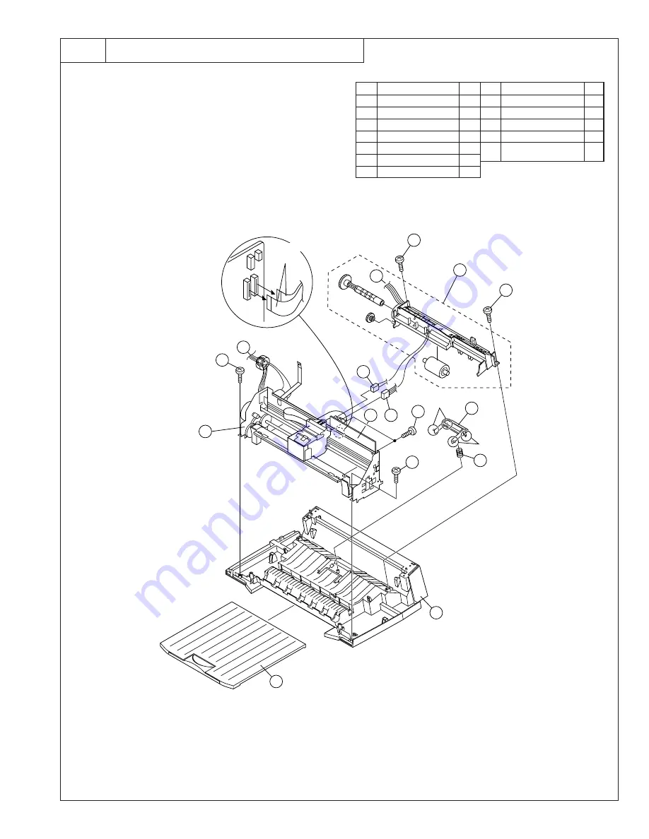
Fig. 6
Printer unit, Bottom cabinet
6
1
2
A
A
1
9
7
5
4
6
3
7
10
Hook
Hook
11
12
8
CNHEAD1/CNHEAD2
cables
Printer unit
Bottom Cabinet
3 – 11
Parts list (Fig. 6)
No.
Part name
Q’ty
No.
Part name
Q’ty
1
Screw (3
×
10)
2
2
Pick up holder unit
1
3
CRMT cable
1
4
FDMT cable
1
5
Screw (3
×
6)
2
6
Printer PWB unit
1
7
Screw (3
×
10)
2
8
Printer unit
1
9
Separate plate
1
10
Separate spring
1
11
Bottom cabinet
1
12
Exit tray/
1
Extension exit tray
NOTE: For disassembly of the inside of the
unit, refer to the exploded view in the
parts guide.
Summary of Contents for UX-A1000
Page 51: ...UX A1000U 3 13 M E M O ...
Page 81: ...UX A1000U Control PWB parts layout Top side 6 8 DRSNS BROWN ORGSNS ORANGE FRSNS RED ...
Page 82: ...UX A1000U Control PWB parts layout Bottom side 6 9 FU101 FU100 ...
Page 86: ...UX A1000U TEL LIU PWB parts layout Top side 6 13 TEL LIU PWB parts layout Bottom side ...
Page 91: ...UX A1000U P IN YELLOW FU1 GREEN 3 3V Printer PWB parts layout Top side 6 18 ...
Page 92: ...UX A1000U Printer PWB parts layout Bottom side 6 19 ...
Page 98: ...UX A1000U FPC FPC Ink PWB parts layout Top side Ink PWB parts layout Bottom side 6 25 ...


