UX-A1000U
(6) IC12 (
µ
PD65944) Hardware description
Serial data reception from FaxEngine
FaxEngine external bus connection
Resolution conversion/image zooming (70 % - 200 %)
Main scan: 203.3 dpi
600 dpi
Sub scan: 97.79 dpi/195.58 dpi/391.16 dpi
600 dpi
Main scanning direction: print position centering
Sub scanning direction: white skip
Printing dot calculation
Printing data: swath conversion
Split printing
IEEE1284 interface (commands/responses)
Autonomous output of printing commands
Buffer memory control (DRAM)/access arbitration
Fax Engine
Serial Data I/F
IF ASIC
Received data
destruction
circuit
Serial data
receiving circuit
203 dpi data
buffer
Blank data
interpolation
circuit
Main scanning
direction
resolution
conversion circuit
Main scan 600 dpi
data buffer
132kB(FIFO)
Sub scanning
direction resolution
conversion circuit
Sub scan 600
dpi data buffer
280kB
Swath data
conversion circuit
ESC command
adding circuit
Memory access
arbiter
DRAM controller
DRAM 4Mbit
Interruptive
controller
Fax Engine
bus interface
Overall data
conversion controller
Conversion completed
Printing dot
calculation/duty
judging circuit
Command buffer
64B(FIFO)
Printer controller
Hurricane
Response buffer
1024B(FIFO)
IEEE1284 controller (compatibility mode, nibble)
IEEE1284 I/F
Fax Engine
CPU Bus I/F
Number of dots
Control
Registers
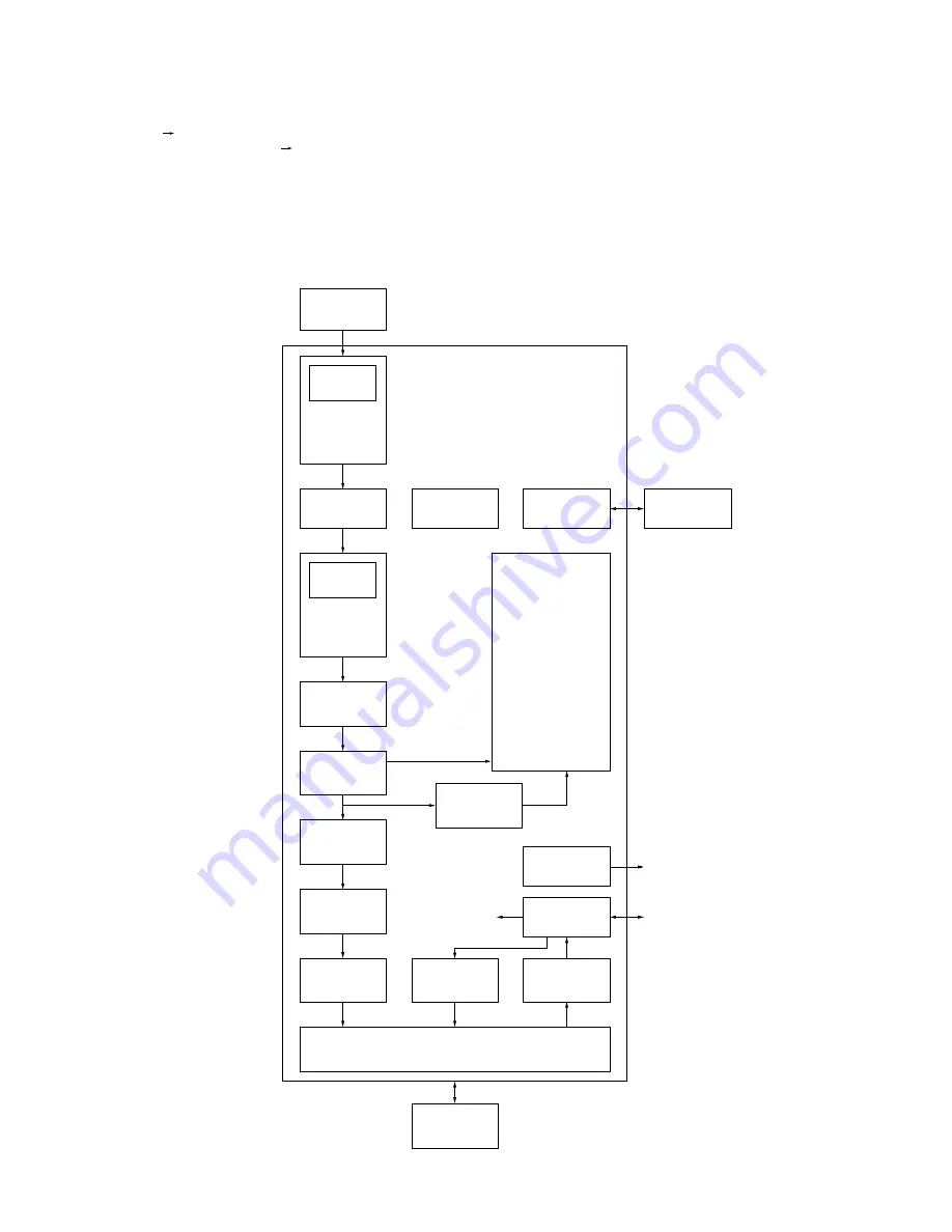
Fig. 5 Configuration of IF ASIC
5 – 9
Summary of Contents for UX-A1000
Page 51: ...UX A1000U 3 13 M E M O ...
Page 81: ...UX A1000U Control PWB parts layout Top side 6 8 DRSNS BROWN ORGSNS ORANGE FRSNS RED ...
Page 82: ...UX A1000U Control PWB parts layout Bottom side 6 9 FU101 FU100 ...
Page 86: ...UX A1000U TEL LIU PWB parts layout Top side 6 13 TEL LIU PWB parts layout Bottom side ...
Page 91: ...UX A1000U P IN YELLOW FU1 GREEN 3 3V Printer PWB parts layout Top side 6 18 ...
Page 92: ...UX A1000U Printer PWB parts layout Bottom side 6 19 ...
Page 98: ...UX A1000U FPC FPC Ink PWB parts layout Top side Ink PWB parts layout Bottom side 6 25 ...


