UX-B20U/UX-B20C/B25C
3 – 3
[2] Ink jet printer
1. Engine specifications
1.1. Mechanism
Resolution:600dpi x 600dpi address ability
Print speed:2.9PPM text with black cartridge
Print swath:8 inches
Duty cycle:250 pages per month average
Dimensions:330mm x 100mm x 130mm
Weight:1.98punds(900g)(1p=453g)
Acoustics:50db in letter quality mode
1.2. Electrical
No electrical hardware included with the type B engine except for the
carrier drive stepping motor, the Sensor FPC assembly which includes
a photo interrupter for sensing home position, the carrier cables, and
the printhead cable.
2. Abbreviations
EOF End-of Form
ESD Electrostatic Discharge
FRU Field Replaceable Unit
HVPS High Voltage Power Supply
LVPS Low Voltage Power Supply
OEM Original Equipment Manufacturer
POST Power-On Self Test
V ac Volts alternating current
V dc Volts direct current
ZIF Zero Insertion Force
3. Diagnostic information
3.1. Print cartridge
Black Print Cartridge 208 Nozzles
Pigment based(Water proof)
initial cartridge
Approx.yield 300 letter pages at 4%coverage
Replacement cartridge:SHARP
UX-C70B
Approx.yield 600 letter pages at 4%coverage
* When Ink Save mode is enabled.
3.2. Start
Power-On Self Test (POST) Sequence
When you turn the printer on it performs a POST. Turn the machine on
and check for a correct POST operation by observing the following:
1. The carrier moves.
2. The paper feed gears turn.
3. After 30 seconds the carrier moves over the maintenance station
and caps the printhead.
4. All motors stop
4. Circuit description
4.1. General description
The compact design of Ink PWB is obtained by using Head Driver IC
and Home position Sensor.
4.2. Electrical system
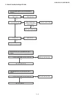
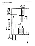
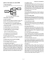
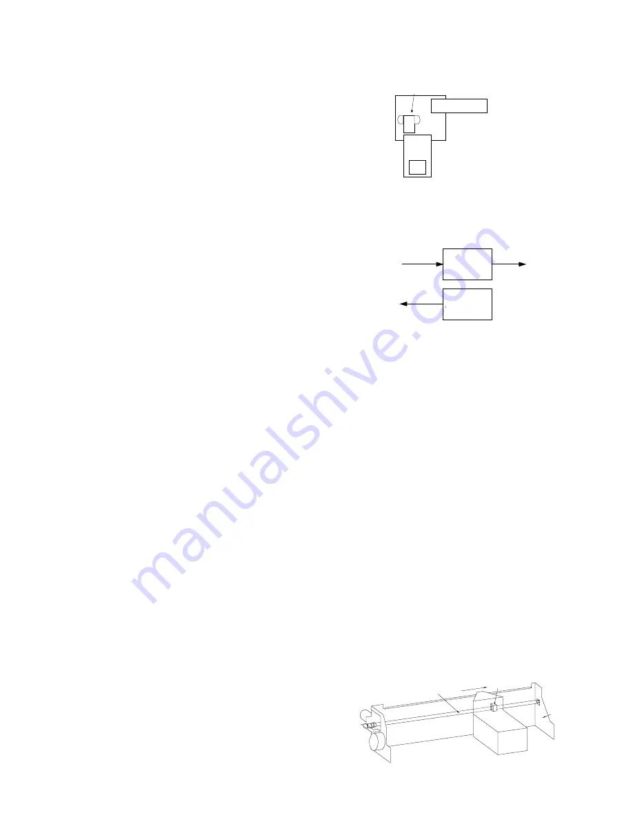
The PWB provides mechanical control for Ink Jet Printer. Fig. 1 shows
the interconnection of PWB and other electrical component in the print
mechanism.
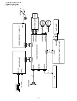
4.3. Electrical overview
The information in this section appears in a sequence relative to the
system diagram in the following figure.
4.4. Power supply connector
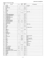
The mechanism requires two voltages (+3.3V, +11.82V and +30V).
These three voltages supplied from CNHEAD1 connector.
4.5. Host interface connector
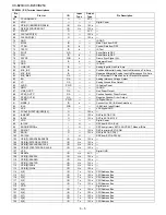
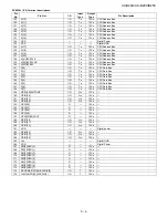
FFC on the Ink PWB provides 23 lines from the host unit, for control of
various operating options available to the host. The two primary func-
tions of the host interface are:
Printing data for the Ink Jet Printer
Error status to the host
4.6. Driver IC
One driver IC drive 208 (MONO) nozzles on the cartridge. This driver
IC, located on the Ink PWB, also connected back to the ASIC, on Con-
trol PWB.
4.7. Ink cartridge carrier
The carriage connects via a FPC on the Ink PWB. The ink cartridge
contacts connect to the carriage contacts. The ASIC controls the car-
riage and ink cartridge.
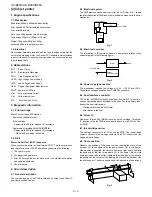
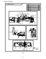
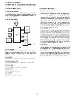
4.8. Home position
Measure the position of the carrier unit by reading the scale of the
encoder ((1) in the figure) with the photo sensor ((2) in the figure).
When power is supplied, the carrier unit moves right until it contacts
the dead-end of the right main frame ((3) in the figure). We call this
home position and hereinafter, regard as the starting point to measure
the position of the carrier unit by reading the scale of the encoder with
the photo sensor. The home position shall be applied to all operations.
Fig. 1
Fig. 2
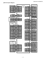
Fig. 3
FFC
Photo Sensor
To
Control PWB
FPC
Driver
Control PWB
Sensor
Home Position
Head
(1)
(2)
(3)
Summary of Contents for UX-B20
Page 2: ... i UX B20U UX B20C B25C ...

