VC-A598U/H995U/H996U
-H997U/H9977U/H998U
41
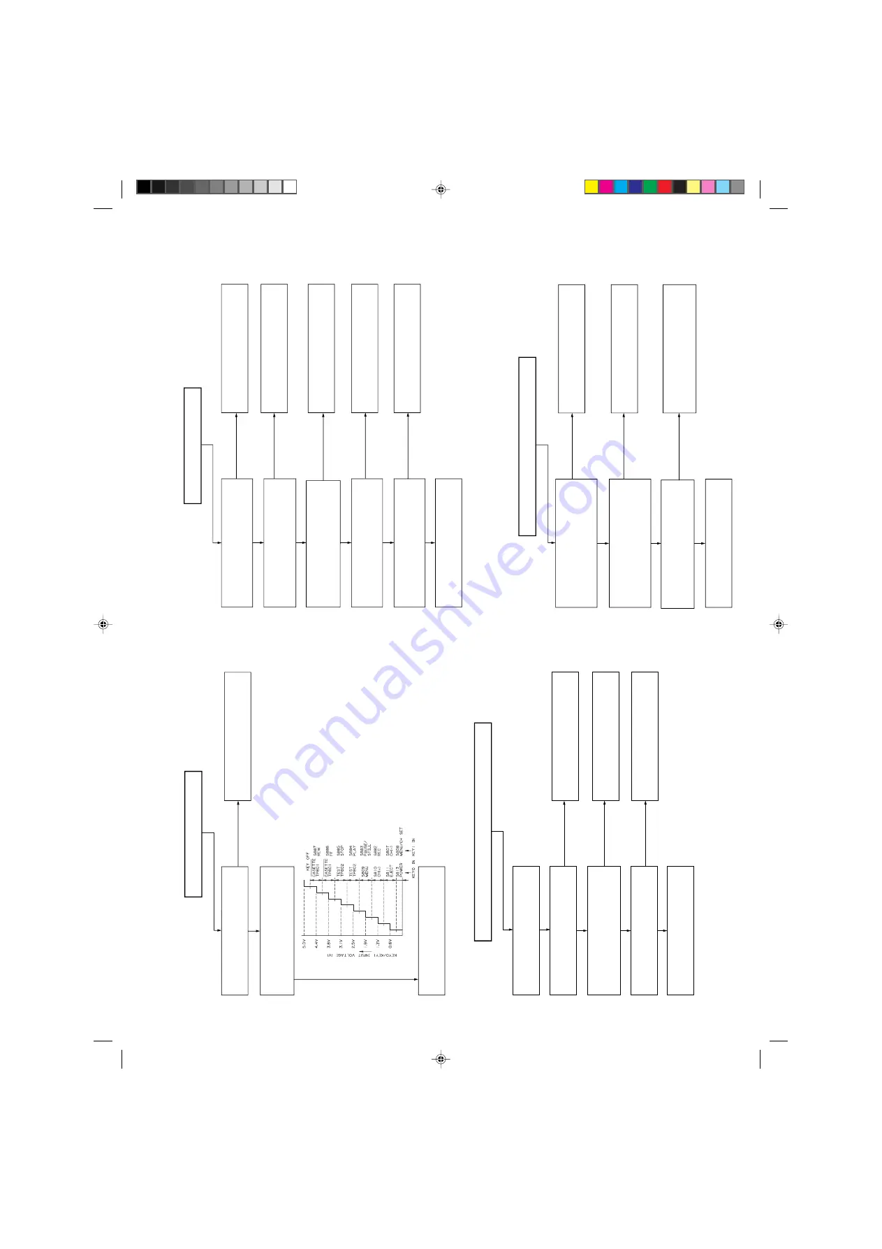
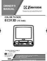
FLOW CHART NO.6
Does the key switch make good
contact, when the cassette tape is
inserted?
Check switch contact.
Is there the function control voltage
inputted at the pins(87) and (88)
of IC701?
Check or place the peripheral circuit
of IC701.
YES
YES
NO
Key-in input is not received.
FLOW CHART NO.8
A cassette tape is not take in.
YES
YES
YES
YES
NO
YES
NO
NO
NO
NO
Check start sensor shutter.
Check line start sensor and all the
way up thru to pin(79) of IC701.
Check line pin(9) of IC701 and all
the way up thru to pin(11) of IC706.
Check IC706.
Check between IC706 and loading
motor.
Replace loading motor.
Is the specified voltage (about 10V)
applied at the loading motor terminal
when the cassette tape is inserted?
Does pin(13) of IC706 change to
about 10V when the cassette tape is
inserted?
Does pin(11) of IC706 go to a "H"
(about 1.7V) level when the cassette
tape is inserted?
Does pin(79) of IC701 change from
"H" to "L" level when the cassette
tape is inserted?
Are start sensor shutter go to open
when the cassette tape is inserted?
NO
NO
NO
FLOW CHART NO.9
A cassette tape is taken in, but ejected at once.
Does the start sensor pulse at
pin(79) of IC701 change from "L" to
"H" level when the cassette tape is
loaded?
Check start sensor and all the way
up thru to IC701.
Does the end sensor pulse at pin(85)
of IC701 change from "L" to "H" level
when the cassette tape is loaded?
Check end sensor and all the way
up thru to IC701.
Does the master cam mode shifter
operate normally when the cassette
tape is loaded?
Check cam switch and all the way
up thru to IC701.
Replace IC701.
YES
YES
YES
FLOW CHART NO.7
No operation is possible from the infrared remote control.
Operation is possible from the VCR,
but no operation is possible from the
infrared remote control.
Is the supply voltage of 5V feed to
pin(3) terminal of remote control
receiver?
Check AT 5V lines.
Is "L" pulse sent out pin(1) terminal of
receiver when the infrared remote
control is activated?
Replace the remote control receiver
or replace the remote control
transmitter if necessary.
Is inputted "L" pulse to pin(5) of
IC701?
Check line between at remote
control receiver thru to pin(5) of
IC701.
YES
YES
NO
NO
NO
YES
Replace IC701.
YES
Summary of Contents for VC-A598U
Page 6: ...VC A598U H995U H996U H997U H9977U H998U 6 1 3 LOCATION OF MAJOR COMPONENTS AND CONTROL ...
Page 51: ...VC A598U H995U H996U H997U H9977U H998U 51 8 BLOCK DIAGRAM POWER CIRCUIT BLOCK DIAGRAM ...
Page 52: ...VC A598U H995U H996U H997U H9977U H998U 52 SYSTEM SERVO BLOCK DIAGRAM ...
Page 53: ...VC A598U H995U H996U H997U H9977U H998U 53 ...
Page 54: ...VC A598U H995U H996U H997U H9977U H998U 54 SIGNAL FLOW BLOCK DIAGRAM VC A598U ...
Page 61: ...VC A598U H995U H996U H997U H9977U H998U 61 13 12 11 10 9 8 7 ...
Page 65: ...VC A598U H995U H996U H997U H9977U H998U 65 13 12 11 10 9 8 7 ...
Page 67: ...VC A598U H995U H996U H997U H9977U H998U 67 13 12 11 10 9 8 7 ...
Page 69: ...VC A598U H995U H996U H997U H9977U H998U 69 13 12 11 10 9 8 7 ...
Page 72: ...VC A598U H995U H996U H997U H9977U H998U 72 7 6 5 4 3 2 1 A B C D E F G H MAIN PWB ...
Page 73: ...VC A598U H995U H996U H997U H9977U H998U 73 13 12 11 10 9 8 7 ...


