44
VC-AA350A/L/M/W
VC-AA352W,AA360A,AA370A
VC-AA550A/L/W,AA560A,AA570A
YES
YES
NO
NO
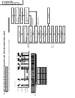
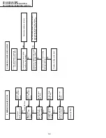
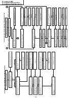
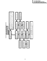
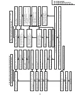
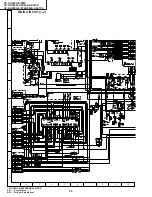
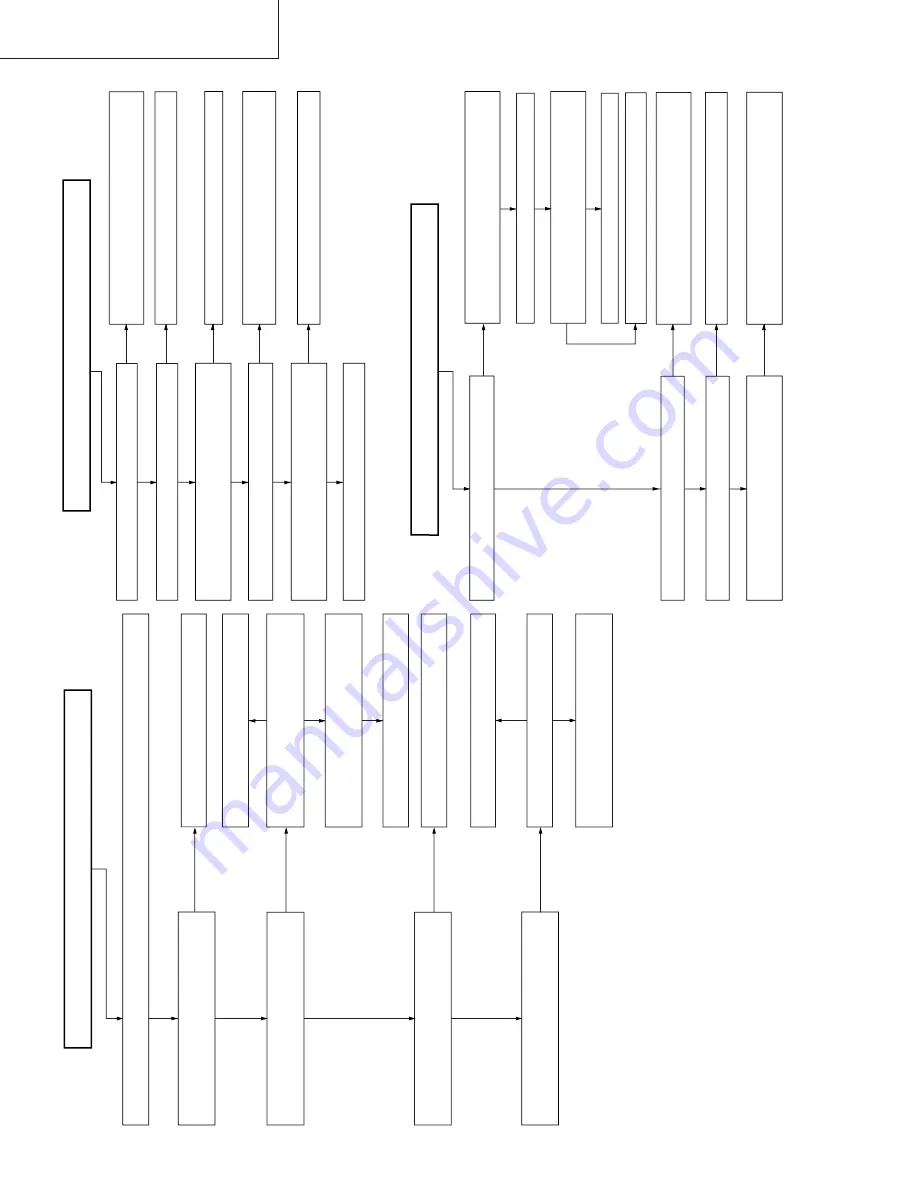
FLOW CHART NO.21 NTSC SKEW TROUBLESHOOTING
YES
NO
NO
NO
YES
Is the supply voltage at pins(3) and (4)
of IC261?
Check PC 5V line.
Dose the circuit around pins(14),(15)
and (16) of IC261 operate normally?
Replace defective parts.
Check line between pin(13) of IC261
and pin(9) of IC701.
Is there a picture signal outputted from
the pin(8) of IC261?
Is there a picture signal inputted to the
pin(9) of IC261?
YES
YES
Check peripheral circuit of Q264.
Is there
H
level at pin(13) of IC261?
No NTSC SKEW function.(PAL playback mode is possible).
Is there a picture signal inputted to the
pin(12) of IC261?
Insert the NTSC systen recorded tape and put the unit in the NTSC playback mode.
Is there a picture signal outputted from
the pin(10) of IC261?
NO
Check EQ amplifier circuit.(Q261,262)
NO
Replace IC261.
NO
NO
NO
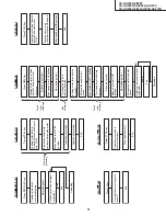
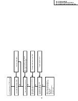
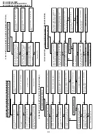
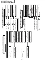
FLOW CHART NO.22 LINEAR SOUND MODE TROUBLESHOOTING (1)
Is there "L" level at pin (99) of IC201?
Is there a signal at pin(4) of IC201?
YES
YES
No linear sound recording (Hi-Fi E-E mode is possible)
Is the supply voltage of 12V fed to pin(2) of
T601?
Check the AUDIO MUTE (H) line between pin
(99) of IC201 and pin (81) of IC701.
Replace IC201.
Check PC 12V line.
NO
YES
YES
Is there signal (Bias) at pin (5) of T601?
Check the Bias oscillation circuit(T601,Q602,
Q603) and FE BIAS CTL line.
NO
Is there signal (Bias + Audio sig.) at pin (6)
of T601?
YES
Check the MH-AM harness and A/C head.
Check peripheral circuits of T601.
YES
NO
NO
NO
NO
NO
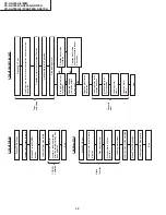
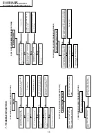
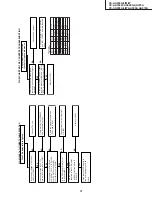
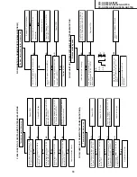
FLOW CHART NO.23 LINEAR SOUND MODE TROUBLESHOOTING (2)
YES
YES
Clean A/C Head.
Is the azimuth height of A/C head properly
adjusted?
Replace A/C head.
Is there "L" level at pin (99) of IC201?
Is there a signal at pin(11) of IC201?
YES
YES
Are the MH-AA harness and the PB AMP.
peripheral parts normal?
Readjust azimuth height.
YES
No linear sound playback (Hi-Fi E-E mode is possible)
Is there a signal at pin(100) of IC201?
Is there audio signal inputted at pin(62) of
IC651?
Check the AUDIO MUTE (H) line between pin
(99) of IC201 and pin (81) of IC701.
Replace IC201.
Check line between pin (11) of IC201 and
pin (62) of IC651.

